Input/output modules
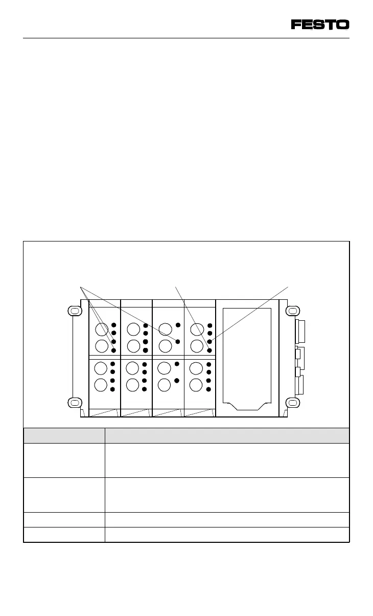
There are one or two LEDs (status displays) next
to the relevant connections on the input/output
modules. The colours of these LEDs are:
• green (status display of digital inputs)
• yellow (status display of digital outputs)
• red (error display of digital outputs)
The current signal at each input/output is shown
by means of the yellow and green LEDs. The
red LEDs of the outputs indicate short circuit or
overload of the relevant output.
Red LEDs
(Short circuit/overload
display of outputs)
Yellow LEDs
(switching status
display of outputs)
Green LEDs
(switching status
display of inputs)
I8 I8 I4 O4
Fig. 5/6: LED displays of input/output modules
LED Status
Yellow out
or
Green out
Logic 0
(no signal)
Yellow alight
or
Green alight
Logic 1
(signal applied)
Red out Output without short circuit/overload
Red alight Short circuit/overload at relevant output
VIFB13 - 03/05 5. Diagnosis/error treatment
5-8
9701 NH