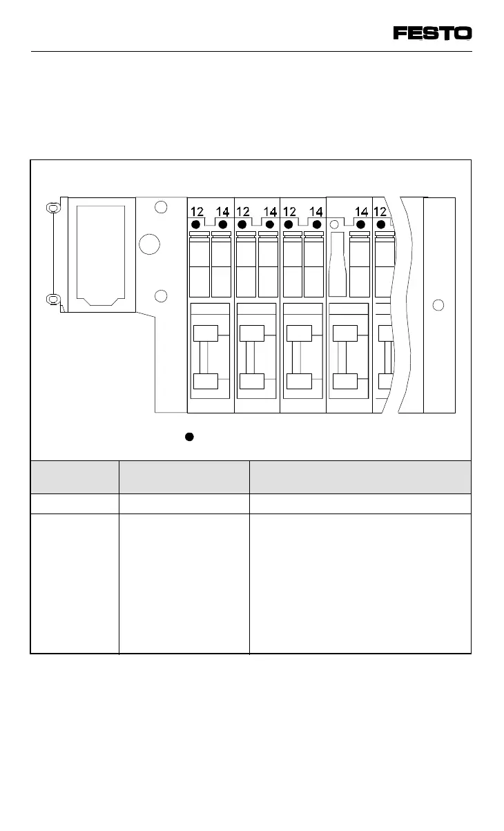
There is a yellow LED for each valve solenoid
coil on the ISO valve terminal. This LED shows
the switching status of the valve solenoid coil.
LED Switching position of
valve solenoid coil
Meaning
Yellow out Basic position Logic 0 (no signal)
Yellow alight • Switch position
or
• basic position
Logic 1 (signal applied)
Logic 1 but:
• operating voltage of outputs is
below permitted tolerance range
(< 21.6 V)
or
• compressed air supply not correct
or
• service case
yellow LEDs
Fig. 5/5: LED display – switching status of ISO valve solenoid coil
VIFB13 - 03/05 5. Diagnosis/error treatment
9701 NH 5-7