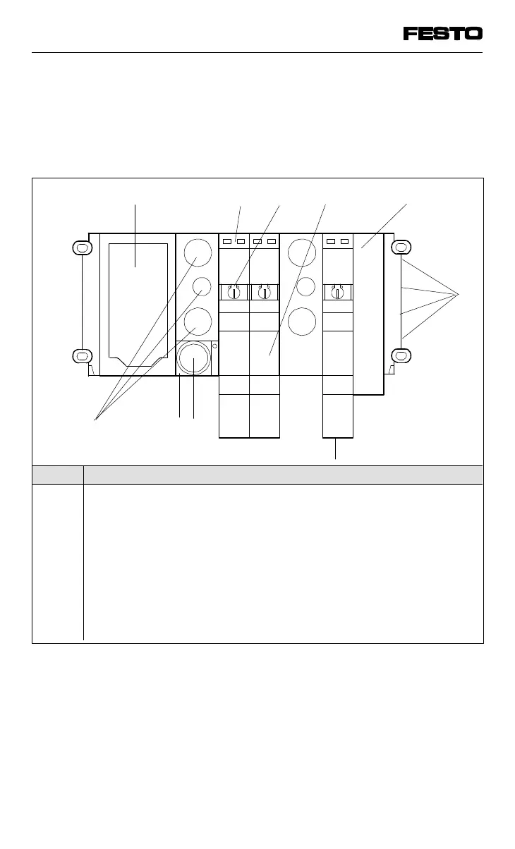
The connections, display and operating elements
shown below are to be found on the MAXI
modules of type 03.
No. Meaning
1
2
3
4
5
6
7
8
9
10
Node with LEDs and field bus interface, detailed description see
chapter "Installation"
Yellow LEDs (per valve solenoid coil)
Manual override (per valve solenoid coil)
Valve location inscription field (signs)
Unused valve location with blanking plate
Common pneumatic tubing connections
Work connections (2 per valve, one above the other)
Pressure regulator for pilot air
Common pneumatic tubing connection
Exhaust connections
3
1
2
4
6
10
5
7
8
9
Fig. 1/5: Operation, display and connection elements of
MAXI modules type 03
VIFB13 - 03/05 1. User instructions
1-8
9701 NH