The 24 V operating voltages are connected at
the adapter plate between the node and the
valves. The operating voltage connection for the
node and the I/O modules is supplied via the
adapter cable.
The following components on valve terminal type
05 are supplied separately + 24 V DC via this
connection:
• the internal electric components and the input
modules (pin 1: DC + 24 V, tolerance ± 25 %
external fuse recommended with max.
3.15 A).
• the outputs of the valves and of the output
modules (pin 2: DC + 24 V, tolerance ± 10 %,
external fuse max. 10 A, slow blowing, re-
quired).
Recommendation
The operating voltage for the outputs/valves
should be connected via the EMERGENCY
STOP circuit or contacts.
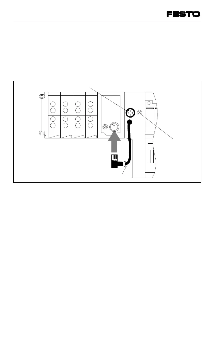
Operating voltage connection type 05
Adapter cable
Fuse for valves
(4A slow blowing)
Fig. 3/12: Position of the operating voltage connection
VIFB13 - 03/05 3. Installation
9701 NH 3-23