PLEASE NOTE
Please note that with common voltage supply
for pin 1 (electronic components and inputs)
and pin 2 (outputs/valves), the lower tolerance
of
±
10 % for both circuits must be observed.
Check the 24 V operating voltage of the outputs
while your system is operating. Please see that
the operating voltage of the outputs lies within
the permitted tolerances even during full oper-
ation.
Recommendation
• Use a closed loop power unit.
• Calculate the complete current consumption
according to the following table and select
both a suitable power unit and cable cross
section.
• Avoid long distances between the power unit
and the terminal. Calculate the permitted
distance according to Appendix A.
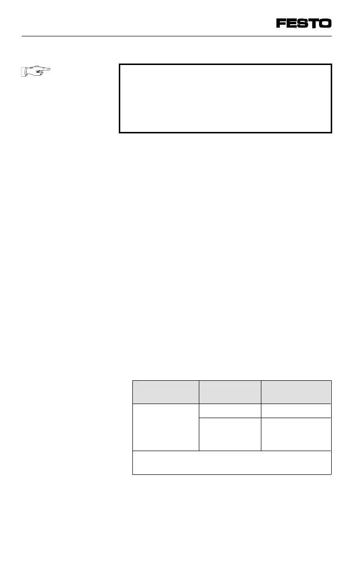
The following rule applies for type 05:
Current
consumption *)
Cable cross
section
Distance
Pin 1 = 2.2 A 1.5 mm
2
≤ 8 m
Pin 2 = 10 A
V
B
= 24 V
2.5 mm
2
≤ 14 m
*) Please note that the max. total current
consumption (pins 1 and 2) is 12.2 A.
VIFB13 - 03/05 3. Installation
3-24
9701 NH