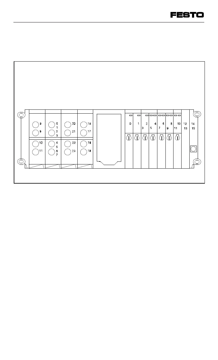
The diagram below shows the address assign-
ment with mixed fitting.
Remarks on the diagram
• If single solenoid valves are fitted onto D-type
sub-base modules, four addresses will be as-
signed for solenoid valve coils; the higher
address in each case then remains unused
(see address 3).
• If unused valve locations are covered with
blanking plates, the addresses are still as-
signed (see addresses 12, 13).
• Due to the 4-bit orientated addressing of the
modular valve terminal, the address of the
last location is always rounded up to four full
bits (unless the fitting already uses the full
four bits). This may mean that two addresses
cannot be used (see addresses 14, 15).
Do not round up
4-input module
8-input module
4-output module
4-output module
D-type sub-base
D-type sub-base
D-type sub-base
Fig. 4/4: Address assignment of a valve terminal with digital I/Os
VIFB13 - 03/05 4. Commissioning
4-14
9701 NH