1. Summary of components
1-4
Festo P.BE-SPC11-SYS-ASI -EN en 0203NH
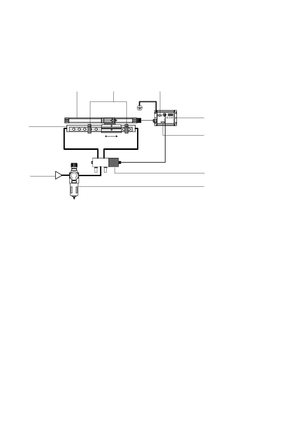
The diagram below shows the basic layout of a drive with the
SPC11 using, as an example, a linear unit with a linear poten-
tiometer.
1
2
34
5
6
7
8
9
1
Drive (linear unit)
2 Measuring system (external linear
potentiometer)
3 Fixed stops
4 24 V DC: Load voltage connection
5 Soft Stop SPC11
6 Bus: A S-Interface bus connection
7 Proportional directional control valve
type MPYE-5-...-...
8 Service unit (without lubricator, with
5 µm filter)
9 Compressed air supply (5...7 bar)
Fig. 1/1: Layout of a dr ive with SPC11 (example linear drive)
With the SPC11, positioning is made with closed-loop control.
During commissioning, the end positions (cylinder end posi-
tionsorpositionofthefixedstops)aswellasthedesired
intermediate positions are “learnt ” by the SPC11.

 Loading...