SERVICE PROCEDURES 48
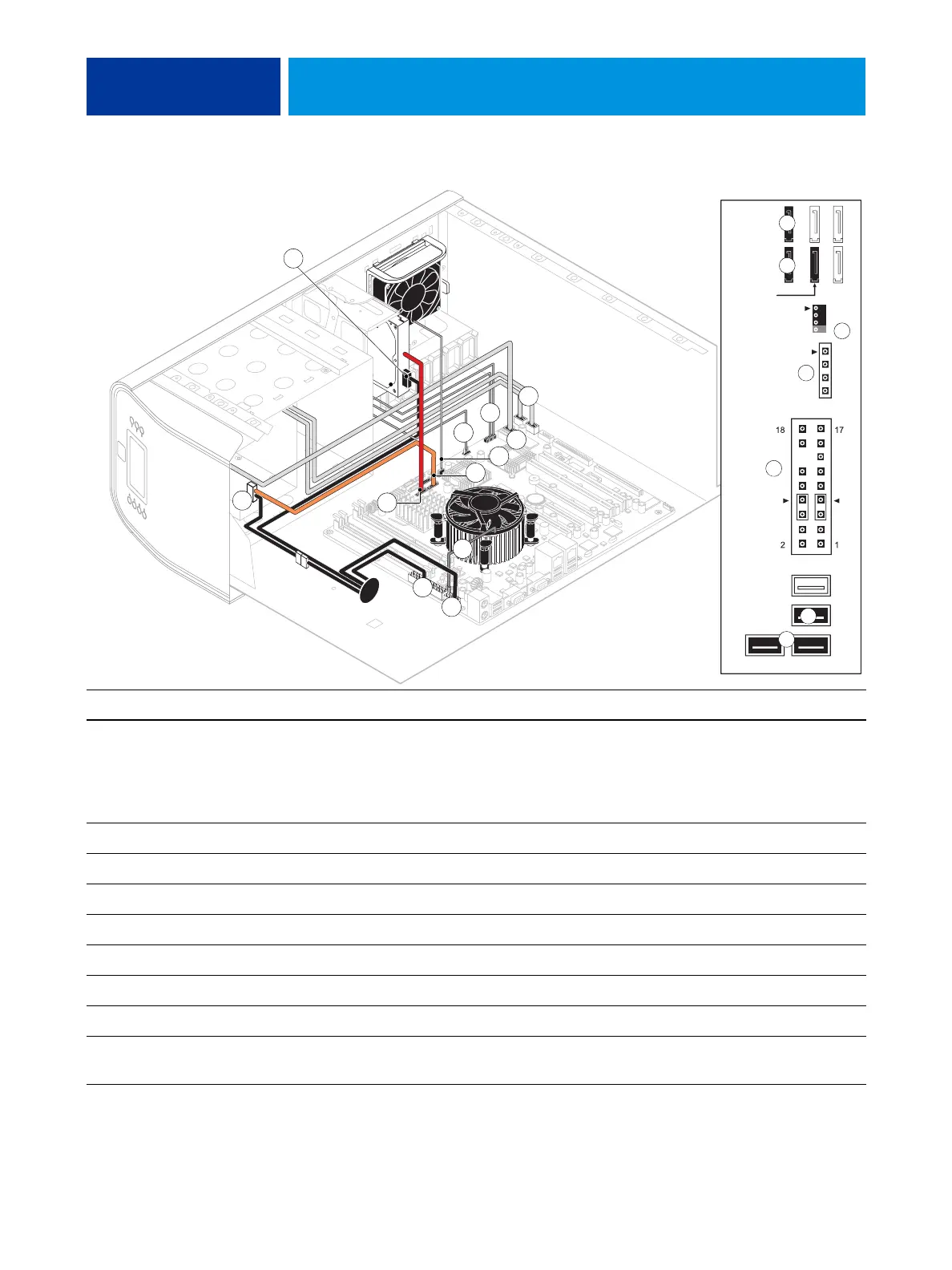
FIGURE 12: Power and data cable connections in the E-41
Cable key From To
1. Power supply cable Power supply a. CPU power connector (PW1)
b. Motherboard power connector (PW2)
c. DVD drive power connector (combined with data)
d. HDD power connector
2. Front panel USB port cables Front panel Motherboard connectors J22, J35 (see detail above)
3. UIB cable User Interface Board Motherboard connector J38 (see detail above)
4. Power and reset cables Front panel Motherboard connector JP4 (see detail above)
5. Speaker cable Front panel Motherboard connector J40 (see detail above)
6. Front panel fan cable Front panel fan Motherboard connector FAN 4
7. DVD drive power/data combo cable DVD drive Motherboard connector SATA 1 (see detail above)
8. HDD data cable HDD Motherboard connector SATA 2 (see detail above)
9. CPU fan cable CPU fan Motherboard connector FAN 1 (If present, keep the
cable cover on the CPU fan cable.)
1b
1c
9
5
NOTE: Power supply, DIMMs, and
ideo board not shown.
87
DVD drive
(SATA 1)
HDD 1
(SATA 2)
HDD 2
(SATA 3;
FAN 4
J40
Speaker
Reset
Power
J22
Front panel USB port cables
J35
J38
JP4
UIB cable
dual-HDD
systems only)
(Orientation of
these ports may vary)
1a
8
4
7
6
4
2
3
5
6
1d
3
7
8
2