INSTALLATION 29
TO CONNECT POWER
1. Connect the recessed end of the E-41 power cable to the power connector on the back of the
E-41 (see Figure 6 on page 28).
2. Connect the other end of the E-41 power cable to a wall outlet.
Make sure to use the correct power cable for your region. Also, to prevent the risk of
cross-talk, make sure that the copier/printer interface cable does not touch the system power
cables. Otherwise, image quality problems or E-41 shutdowns could result.
TO CONNECT TO THE COPIER/PRINTER
1. Make sure that the E-41 and the copier/printer are powered off.
2. Connect one end of the copier/printer interface cable to the lower RJ-45 port on the E-41
back panel.
3. Connect the other end of the copier/printer interface cable to the copier/printer.
Make sure that you connect the cable to the correct RJ-45 port (see Figure 6 on page 28). The
network and copier/printer interface cables look similar but are not interchangeable. The
copier/printer interface cable included with the E-41 is a 39.3 ft. Ethernet crossover cable that
connects to the lower RJ-45 port on the E-41 back panel. The network cable at the customer
site is a straight-through Ethernet cable that connects to the upper RJ-45 port on the E-41
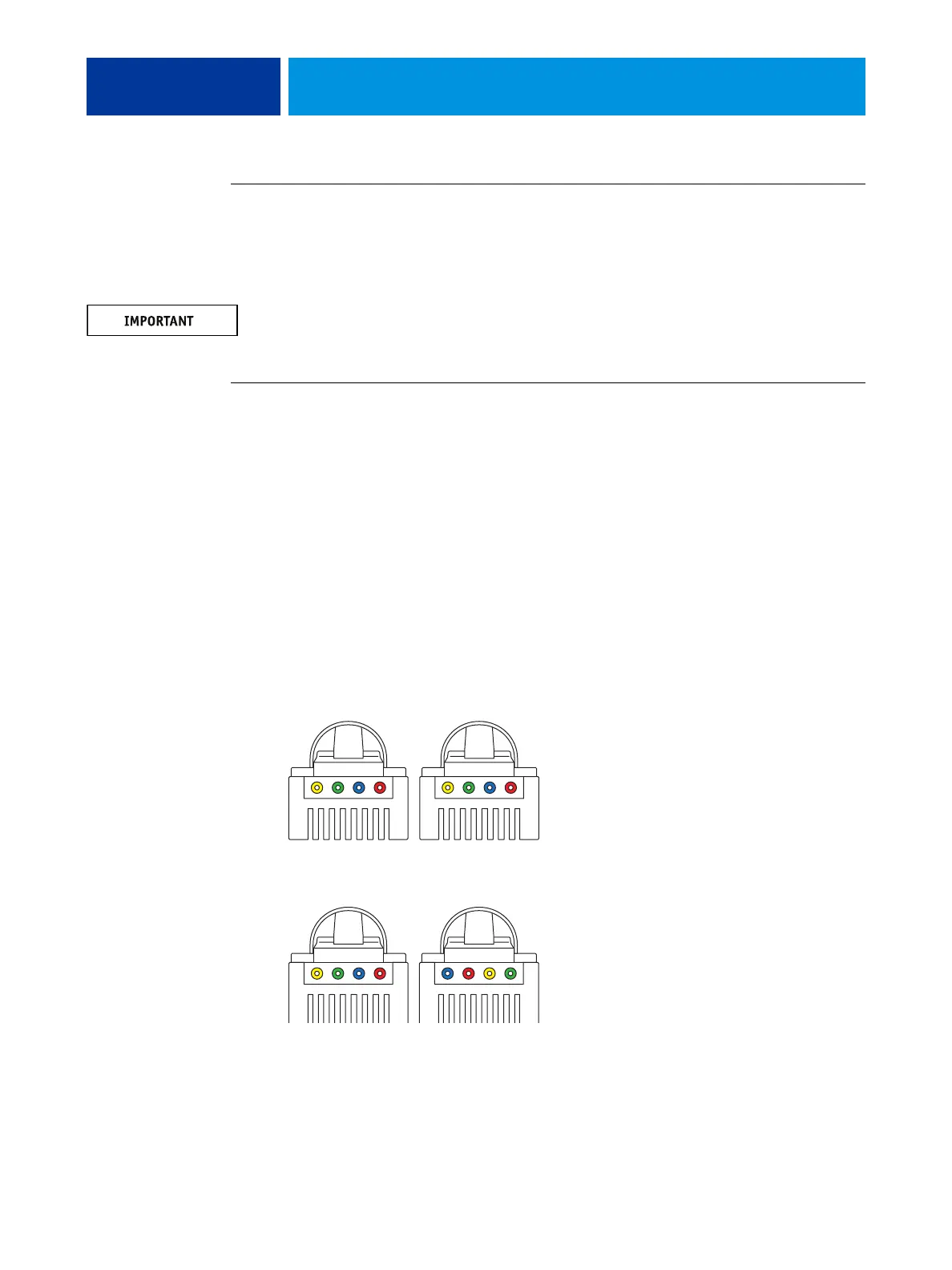
back panel. To verify the cable type, align the connectors on each end of the cable as shown in
Figure 7. On a straight-through cable, the wire arrangements are identical on both ends; on a
crossover cable, the wire arrangements are different.
FIGURE 7: Straight-through and crossover Ethernet cables
1
234
1
234=
Straight-through cable:
wire arrangements are
identical on both connectors
Crossover cable:
wire arrangements are different
Align cables side by side
and examine wires.