SERVICE PROCEDURES 87
Power supply
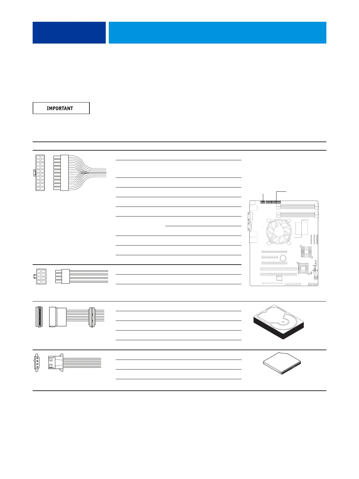
The following table describes the power supply cables that connect to E-41 components. For
more information on the power supply, see “Specifications” on page 144.
Do not open the power supply for service or troubleshooting. Opening the power supply will
void the warranty.
TABLE 1: Power supply cable details
Cable connector Pin(s) Wire color Voltage Connection
NOTE: All voltages listed in this table are direct current voltages (VDC).
1, 2 Orange +3.3V
3, 5, 7, 13, 15,
16, 17
Black COM
4, 6, 19, 20 Red +5V
8GrayPW-OK
9Purple+5Vsb
10 Yellow +12V
11 Orange +3.3V
Brown +3.3V sense
12 Blue -12V
14 Green PS-ON
18 White -5V
1, 2, 3, 4 Black COM
5, 6, 7, 8 Yellow & Black +12V
1 Yellow +12V
2 Black COM
3Red+5V
4 Black COM
5 — not connected
1 Yellow +12V
2 Black COM
3 Black COM
4Red+5V
10
9
8
7
6
5
4
3
2
1
20
19
18
17
16
15
14
13
12
11
20-pin ATX power connector
to motherboard
24-pin
ATX connector
8-pin CPU
4
3
2
1
8
7
6
5
8-pin CPU power connector
to motherboard
SATA (5-pin) power
connector to HDD
4-pin PATA power connector
to DVD drive power/data combo cable