SERVICE PROCEDURES 99
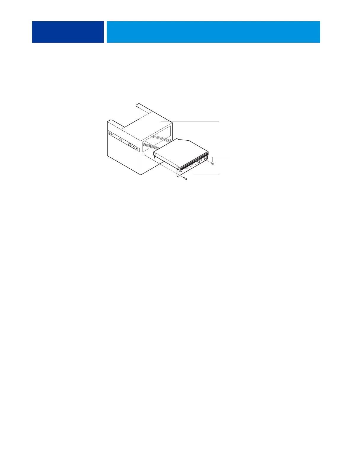
6. Remove the switch bank assembly from the Component Sled.
• Remove the three screws that attach the switch bank assembly to the Component Sled.
• Pull the switch bank assembly straight out of the Component Sled.
FIGURE 36: Removing/replacing the switch bank assembly
NOTE: Guide the cables as you remove the assembly from the Component Sled. Be careful not
to damage the EMI gasket around the opening in the Component Sled.
7. If you are removing the switch bank assembly to replace it with a new assembly, remove the
DVD drive (see page 102).
Component Sled
Switch bank assembly
Screw (1 of 3)