SERVICE PROCEDURES 56
Removing and replacing boards
This section includes procedures for removing and replacing the following boards:
• Video board
• User Interface Board
• Motherboard
The E-41 is shipped from the factory with a standard board configuration, as shown in
Figure 10 on page 46. If optional components have been installed, see the documentation
that accompanies the particular option kit.
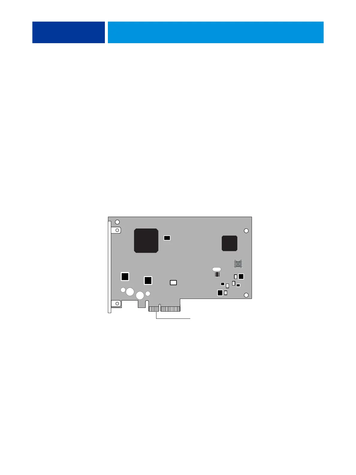
Video board
The video board is installed in motherboard connector J12. The video board processes the
image data and sends it to the copier/printer through a crossover cable connected to the lower
RJ-45 port on the E-41 back panel.
FIGURE 16: Diagram of the video board
To motherboard connector J12