SERVICE PROCEDURES 58
User Interface Board assembly
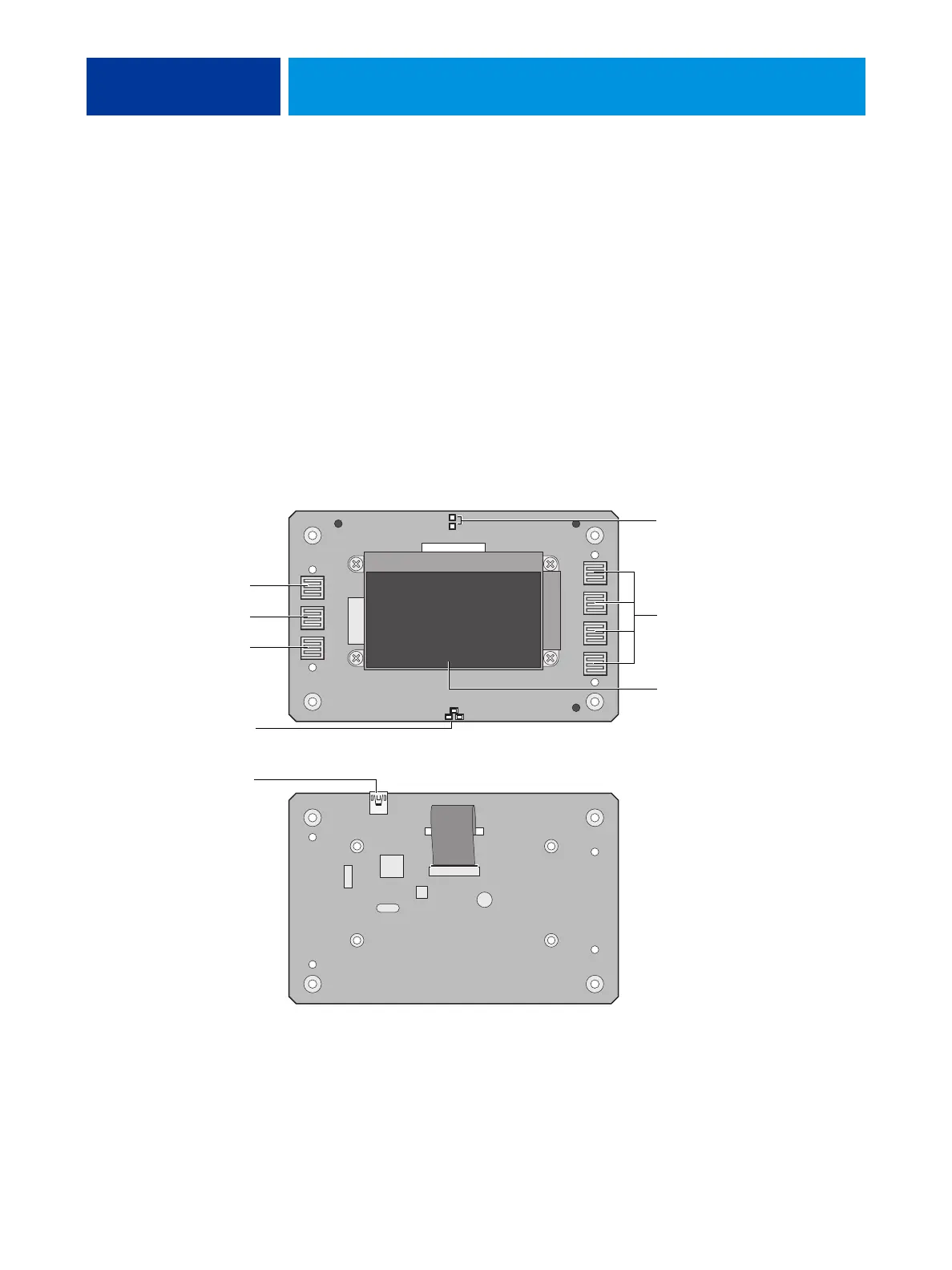
The User Interface Board (UIB) provides the interface between the E-41 and the user. The
front of the UIB contains circuitry for the following:
• Activity lights (amber, green, and red LEDs)
•Display window (LCD)
• Four line selection buttons
• Up and Down buttons
• Menu button
•Jewel lights
The UIB cable is routed from a connector on the back of the User Interface Board to
connector J38 on the motherboard (see Figure 20 on page 62).
FIGURE 17: Diagram of the User Interface Board (front and back)
Back
Front
Line selection
button pads
UIB cable connector J38
Activity lights
(LEDs)
Display window
Up button pad
Menu button pad
Down button pad
Jewel lights