LIST OF FIGURES 7
LIST OF FIGURES
FIGURE 1: Printing system 19
FIGURE 2: E-41 functional diagram 21
FIGURE 3: Summary of installation steps and references 23
FIGURE 4: E-41 shipping contents 27
FIGURE 5: Affixing the decal to the copier/printer 27
FIGURE 6: E-41 connections 28
FIGURE 7: Straight-through and crossover Ethernet cables 29
FIGURE 8: E-41 Control Panel 32
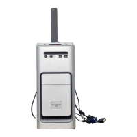
FIGURE 9: Front and back panels 45
FIGURE 10: Back panel and internal side view 46
FIGURE 11: Exploded view of E-41 components 47
FIGURE 12: Power and data cable connections in the E-41 48
FIGURE 13: Removing/replacing the side panels 52
FIGURE 14: Removing/replacing the front panel 53
FIGURE 15: Removing/replacing the top panel 54
FIGURE 16: Diagram of the video board 56
FIGURE 17: Diagram of the User Interface Board (front and back) 58
FIGURE 18: Removing/replacing the User Interface Board 59
FIGURE 19: Removing/replacing the UIB buttons 60
FIGURE 20: Diagram of the E-41 motherboard 62
LIST OF FIGURES