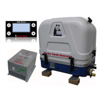
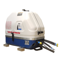
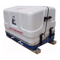
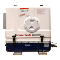
Installation Instructions
22.10.19 Kapitel/Chapter 5: Installation Instructions - Seite/Page 75
Fig. 5.7.3-2: Testing the cooling water levelIf there are any doubts, a verification can easily be made
by temporarily using a clear-sighted hose (1) as exhaust
hose. In that way, the cooling water level can be checked
very easily.
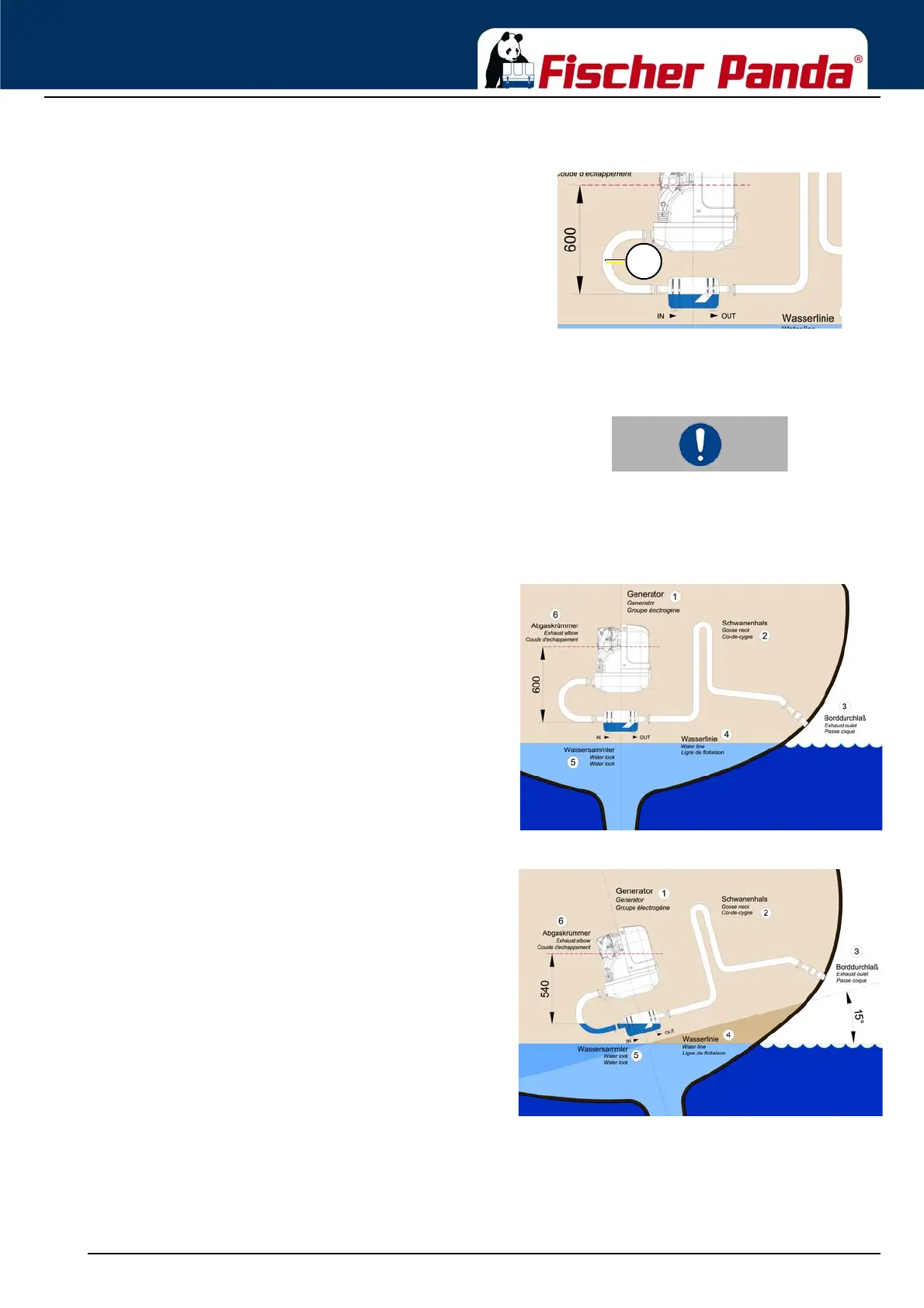
5.7.3.1 Ideal position of the waterlock
Important Note!The ideal position of the waterlock would be in center
underneath the generator.
Only in this position it is assured that the water level cannot
change drastically in tilted position by the waterlock moving
out of the center line.
See the following pictures:
Fig. 5.7.3.1-1: Ideal position of the waterlockIn Fig. 5.7.3.1-1, the waterlock is mounted in center
underneath the generator.
When the ship tilts, the position of the waterlock related to the
critical point at the exhaust hose, changes only slightly.
Fig. 5.7.3.1-2: Tilted position 15 degreesTilted position 15 degrees - Fig. 5.7.3.1-2
The distance from the exhaust elbow to the hydrostatic head
has derated to 540 mm.