Installation Instructions
Seite/Page 76 - Kaptitel/Chapter 5: Installation Instructions 22.10.19
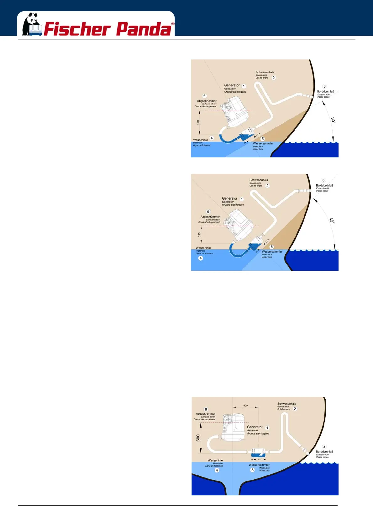
Fig. 5.7.3.1-3: Tilted position 30 degreesTilted position 30 degrees - Fig. 5.7.3.1-3
The distance of the water level, even in ideal position,
changes that only 458 mm distance remain. So the critical
distance is under-run already.
Fig. 5.7.3.1-4: Tilted position 45 degreesTilted position 45 degrees - Fig. 5.7.3.1-4
In this case the water level rise so high, that the distance
constitutes only 325 mm.
Even when the water lock is mounted in the ideal spot, at an
extremely tilted position of 45 degrees there is still the risk
that water can get straight into the discharge stack area
through strong rocking motions („sloshing“). This shows that
the distance of 600 mm represents a minimum size at which,
even when installed ideally, the water can slosh into the
exhaust elbow when the ship is very tilted or rocks very hard.
Summary:
The preset minimum height of 600 mm must be regarded unconditionally and is only valid if the waterlock is
mounted in its ideal position in center underneath the generator. A higher position is highly recommended if it has to
be reckoned with tilted positions of 45 degrees.
5.7.3.2 Example of the installation of the waterlock off-center and possible effects:
The following pictures are primarily relevant for an installation of the generator with the waterlock on sailing yachts.
A change in the mounting position caused by tilted position does not have to be reckoned concerning motor yachts.
Here it is only necessary to regard that the volume of the waterlock is measured so large that it can take the entire
amount of water flowing back, and at the same time, maintains the minimum distance of 600 mm.
A) Installation of the waterlock 500 mm next to the generator’s center line:
Fig. 5.7.3.2-1: waterlock, 500 mm next to the center lineInstallation of the waterlock 500 mm next to the
generator’s center line