Installation Instructions
22.10.19 Kapitel/Chapter 5: Installation Instructions - Seite/Page 77
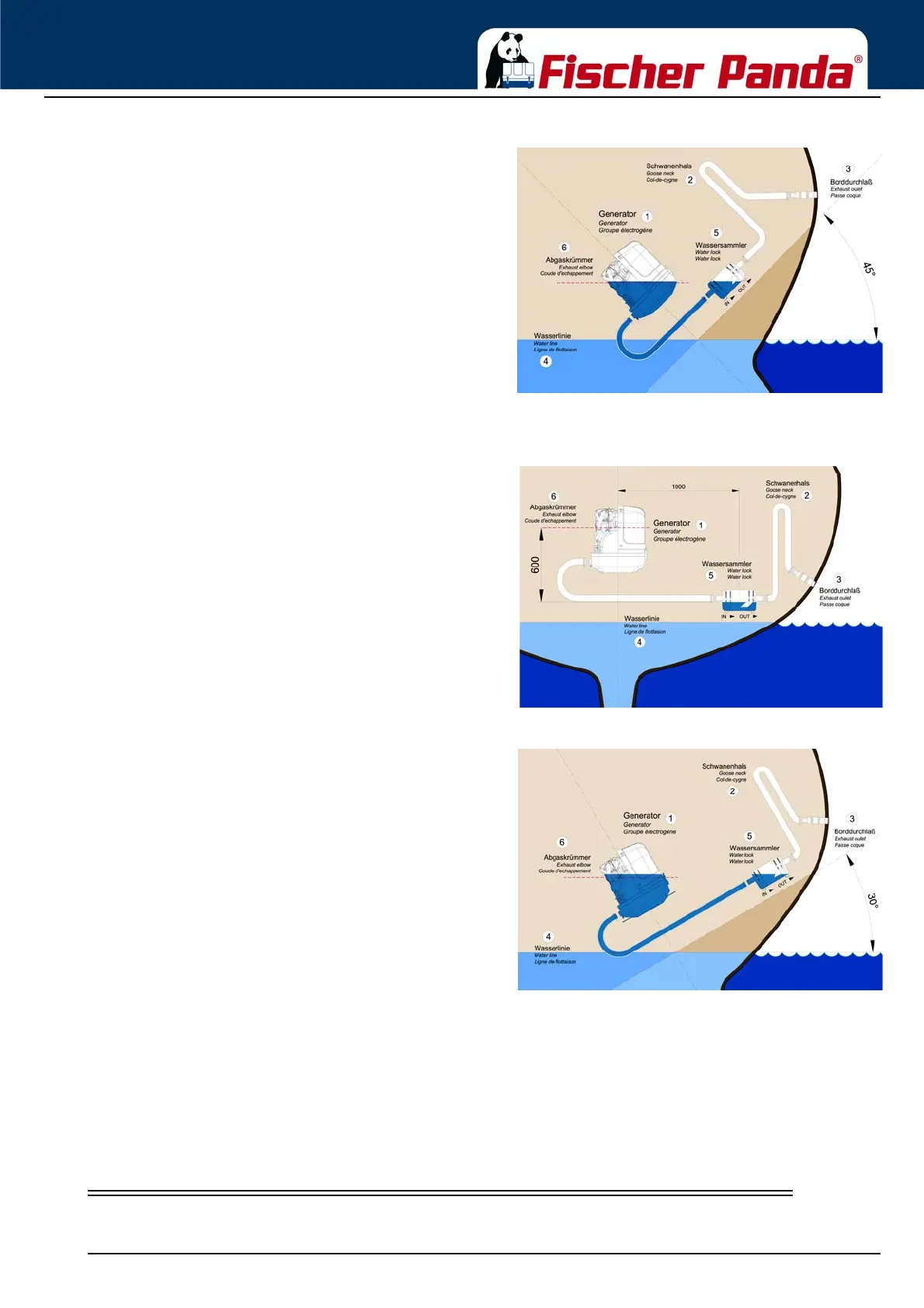
Fig. 5.7.3.2-2: Tilted position 45 degreesTilted position 45 degrees - Fig. 5.7.3.2-2
The water level is now at the same height as the critical point
at the exhaust elbow. If the ship is sailed in a tilted position of
45 degrees with an installation like this, the ingress of cooling
water into the combustion chamber is inevitable. Irreparable
damages are pre-programmed.
B) Installation distance between waterlock and the generator’s center line 1000 mm
Fig. 5.7.3.2-3: waterlock, 1000 mm next to center lineInstallation distance between waterlock and the
generator’s center line 1000 mm
Fig. 5.7.3.2-4: Tilted position 30 degreesTilted position 30 degrees - Fig. 5.7.3.2-4
The water level and the critical point at the exhaust elbow are
at the same level now. If the ship is sailed in a tilted position
of 30 degrees with an installation like that, the infiltration of
cooling water into the combustion chamber is inevitable.
Irreparable damages are pre-programmed.
Summary:
Concerning sailing yachts it must be regarded, that the waterlock is mounted in center underneath the generator, at
least in reference to the ships’ center line. Thus the waterlock is prevented from „leaking“ very strongly when the
ship is tilted.
The „leaking“ of the waterlock leads to a rise of the water level which then gets too close to the exhaust elbow’s
critical point.
5.8 Exhaust / water separator
In order to reduce the noise level of the generator unit to a minimum, an optional exhaust outlet muffler can be