Do you have a question about the Fisher & Paykel AQUASMART WL37T26CW2 and is the answer not in the manual?
| Model | WL37T26CW2 |
|---|---|
| Type | Front Load Washer |
| Capacity | 7 kg |
| Spin Speed | 1200 RPM |
| Width | 600 mm |
| Height | 850 mm |
| Number of Programs | 8 |
| Color | White |
| Water Rating | 4 Star |
| Wash Cycles | 8 |
| Noise Level (Wash/Spin) | 76 dBA / 76 dBA |
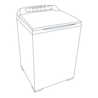
Explanation of the new Fisher & Paykel model numbering system.
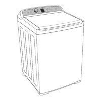
Detailed physical dimensions of the AquaSmart washer.
Water usage per load and approximate factory water fill temperatures.
Details on wash motor, pump motor, and water valve resistances.
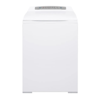
Specifications for cabinet, lid, top deck, inner basket, and console.
Information on bleach and fabric softener dispenser capacities and notes.
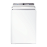
Descriptions of LCD and LED control panel variants.
Important torque specifications for assembly and disassembly.
Process of saturated clothes with concentrated detergent solution.
Front-loader style wash using minimal water for optimum soil removal.
Top-loader style immersion wash suitable for specific wash problems.
Description of buttons and functions on the LCD control panel.
Description of buttons and functions on the LED control panel.
Details on the specific Motor Control Module and its function.
How the machine enters and exits low power standby mode.
Explanation of the electronic system for detecting load imbalance.
Location and function of the thermistor for water temperature measurement.
Description of water valve assembly and dispensing hose connections.
Operation of detergent, bleach, and softener dispensing cycles.
Function of the inlet nozzle and pressure sensing for water level determination.
Specifications and identification of the stator and rotor assembly.
Function and testing of the Rotor Position Sensor.
Overview of the SmartPump system, hood, cap, and flapper valve.
Details on pump housing assembly and rotor/stator interaction.
List of spare parts and explanation of the Simplified Leak Recirculation feature.
Methods for testing the pump stator resistance from the console.
Procedure for testing pump modes and understanding bypassing faults.
Operation and troubleshooting of the lid lock system.
Function of the neck ring and components of the inner/outer tub assembly.
Basket float checks, balance ring, and inner basket base details.
Description and importance of the robust suspension rods.
Details on the low profile agitator and the new control panel design.
Components of the control panel housing, facia, and PCB.
Expected DC and AC voltage readings for various components.
Expected resistance values for key components like valves, motor, and thermistor.
Displaying warning status, fault status, and machine status.
Information on machine size, water level, temperature, and component status.
Managing hot bowl flag, restart, and recycle features.
Enabling, disabling, and identifying restart and recycle features.
Permanently setting features and activating data download.
Procedure to activate and exit showroom mode.
Interpreting fault codes using binary values displayed on LEDs.
Testing individual components like valves and pumps via diagnostic mode.
Managing the hot bowl flag and controlling the restart feature.
Procedure for turning the recycle feature on and off.
Setting restart/recycle features permanently for dispensing and non-dispensing models.
Understanding LED states indicating restart/recycle feature selection.
Activating data download and using diagnostic level tables.
Detailed explanations for various diagnostic information levels.
Procedure to access and exit showroom mode on LED models.
Faults related to motor control module, size, and temperature sensors.
Faults concerning dispensing type, valves, and flood protection.
Troubleshooting water leaks and pump blockage errors.
Faults related to pressure sensor, basket engagement, and display memory.
Faults for valve coils, basket checks, and EEPROM write issues.
Faults related to motor control, pressure transducer, and communications.
Errors involving motor current, pump thermistor, and motor stalling.
Faults related to agitation, EEPROM, and communication timeouts.
Faults concerning lid lock, temperature sensor, and stepper motor.
Faults related to SmartPump operation, flapper, and bleach valve.
Errors related to SmartPump top-up and timeout faults.
Faults for pump sync, bridge test failure, and outdated motor control versions.
Steps to access components located within the console area.
Procedure for safely removing the display module.
Detailed steps for removing the motor control module.
Instructions for removing the inlet valve assembly.
Procedure for removing the thermistor from the valve assembly.
Steps for disconnecting and removing the power cord set.
Instructions for removing the lid lock mechanism.
Procedures for raising and removing the top deck assembly.
Steps to remove softener/bleach funnel and detergent cover.
Procedures for removing dispensing hoses, straps, and neck ring.
Instructions for removing the low profile agitator and its cap.
Steps for removing the inner basket and clutch mechanism.
Procedure for removing the pump hood and cap for inspection.
Steps for removing the stator and pump housing.
Procedure for removing the recirculation hose.
Steps for removing the outer tub assembly and the rotor.
Procedures for removing the stator and rotor position sensor.
Procedure for drilling alternate holes if pump housing bolts strip.
Steps to clear blockages in the pump system.
Procedures and tool kit for shaft and bearing replacement.
Steps for correctly assembling the shaft and bearings.
Causes and solutions for creasing, linting, poor soil removal, and residue.