150718 PLYFLY rev A_Steer spindle | A ug us t 7, 20 15 5: 06 PM
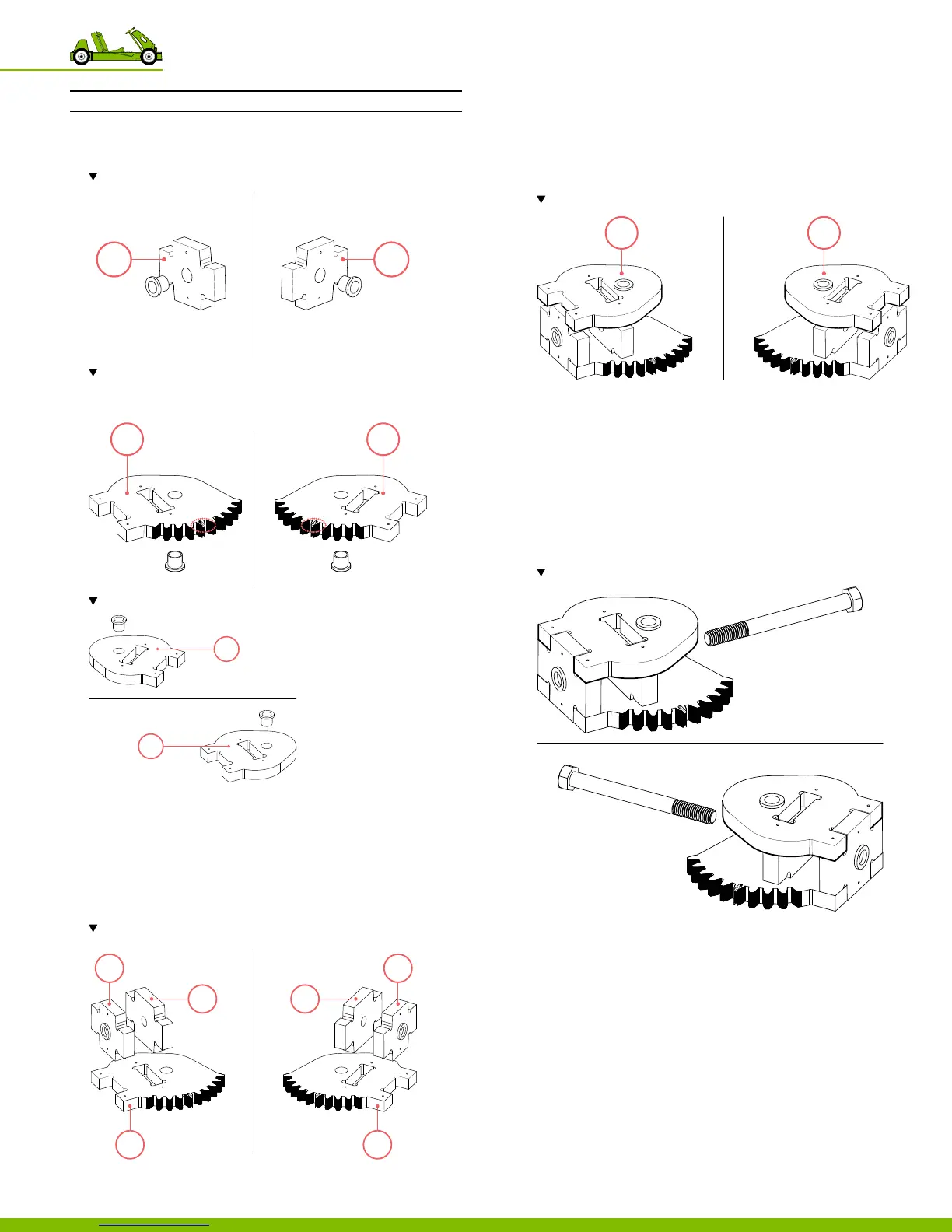
1. Press bushings into parts 1‑2, 5‑6, & 7‑8
Note the orientation of part 1 & 2.
Note Be sure to insert the bushing on the opposite side of the alignment mark.
Parts 5 & 6 are left and a right side biased.
Note the location of the bushings.
2. Using a hammer, tap the bushings until the top is ush
with the wooden part.
3. Using a mallet, tap parts 1 into the outer slot on part 5.
4. Using a mallet, tap parts 2 into the outer slot on part 6.
5. Using a mallet, tap parts 3 into the inner slot on part 5.
6. Using a mallet, tap parts 4 into the inner slot on part 6.
Note the location of the bushings. The bushing should face outwards.
Try to ensure 90°
7. Using a mallet, cap the parts 1, 3, 5 with part 7.
8. Using a mallet, cap the parts 2, 4, 6 with part 8.
Note the location of the bushings.
9. Secure the parts using screws on each part.
‒ Use 2 screws on part 5
‒ Use 2 screws on part 6
‒ Use 4 screws on part 7
‒ Use 4 screws on part 8
‒ Total 20 locations, 20 screws.
10. Using a hammer, insert the 5/8” long bolt into each
steering spindle assembly.
Note the location of the bushings
2
1
5 6
7
8
2
6
4
1
5
3
87
Assembling the left & right steering spindles
INSTRUCTIONS
24
7 Steering Spindle Assemblies