150718 PLYFLY rev A_GoKart | Aug ust 7, 2 015 5 :08 PM
Part 1 Install the rear axle
INSTRUCTIONS
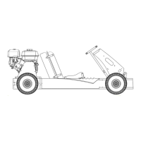
1. Assemble the hub and brake disc using the
button head screws and locknuts.
‒ Use 4 button head screws and 4 locknuts
‒ Total of 4 locations.
Note orientation of the parts.
2. Loosen set screws on all 3 of the mounted bearings
‒ Be sure no screw extends into the interior
of the bearings; as this will prevent
the drive shaft insertion.
3. Insert the drive shaft and bolts
‒
SINGLE WHEEL KIT; continue to step 4.
‒
LIVE AXLE KIT; continue to step 5.
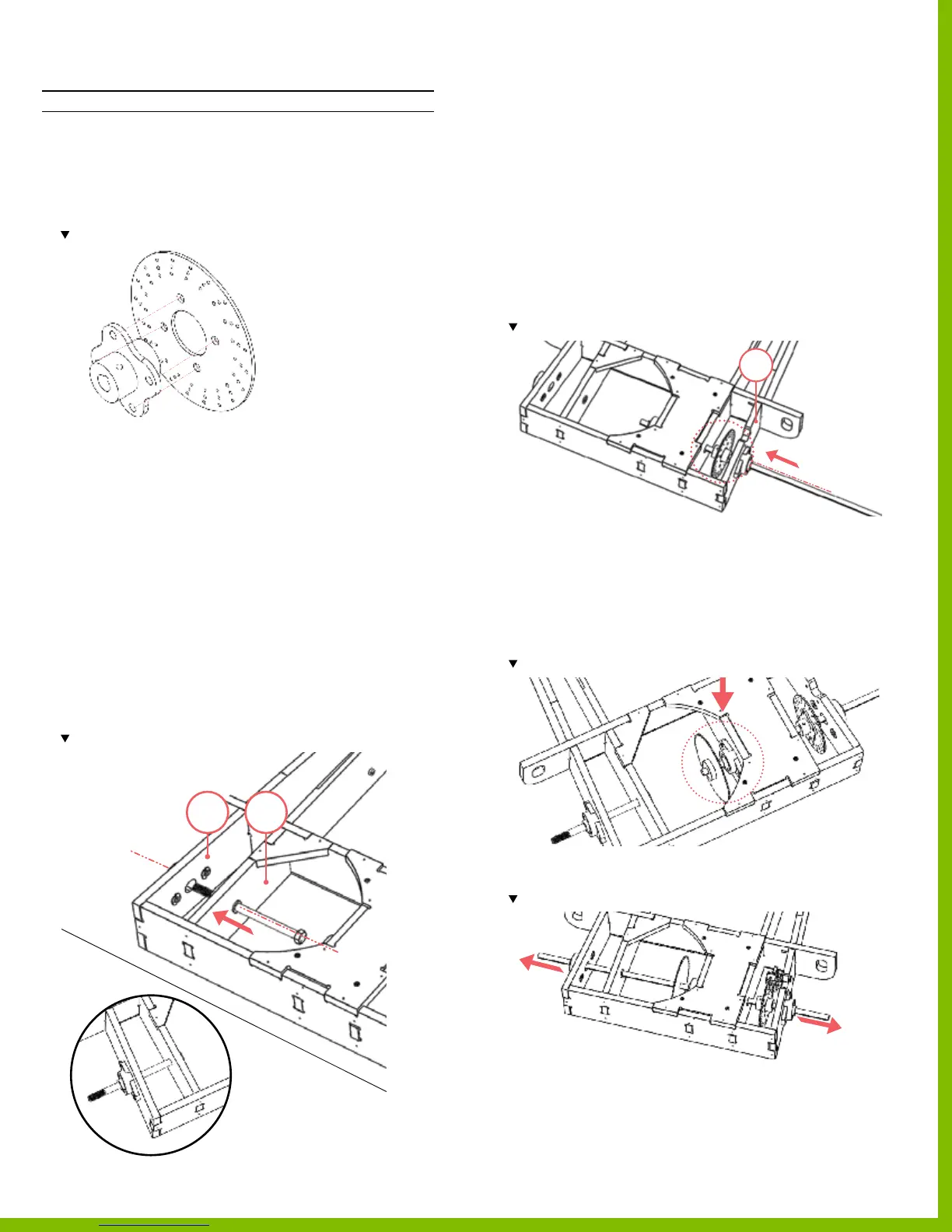
4. Insert the long hex bolt from the interior of the frame
through the bushing located on part 40 and the
mounted bearing located on part 42.
‒ If there is too much resistance to insert the
long hex bolt, temporarily loosen the mounting screws
so the mounted bearing is loose; or remove the
mounted bearing, slide the long hex bolt through and
then re‑mount the mounted bearing.
Note location of the long hex bolt.
5. Insert the drive shaft by sliding it through
the outer mounted bearing located on part 43 only.
‒ If there is too much resistance to insert the
drive shaft, temporarily loosen the mounting screws
so the mounted bearing is loose; or remove the
mounted bearing, slide the drive shaft and then
re‑mount the mounted bearing.
‒ Rotate the bearing in its seat so that it is parallel to the
center frame rails.
6. Once the drive shaft is through the outer
mounted bearing, insert the brake disc on the end.
‒ Use the key to lock the brake disc to the drive shaft.
Note the orientation of the disc brake.
7. Continue to slide the drive shaft through the assembly,
through the center mounted bearing, and then insert the
sprocket on then end.
‒ Use the key to lock the brake disc to the drive shaft.
‒
SINGLE WHEEL KIT is complete.
‒
LIVE AXLE KIT continue to step 8.
Note location and orientation of the bushing
8. Continue to insert the drive shaft through the assembly
and through the nal mounted bearing located on part 42.
Note the drive shaft extends equal distances on both sides of the assembly.
9. Ensure all the hardware on mounted bearings are fully
tightened
.
4042
43
43
PlyFly Go‑Kart Instruction Guide • 2015 Release