150718 PLYFLY rev A_GoKart | Aug ust 7, 2 015 5 :08 PM
Chapter 10
5
PART
Recommended tools
DESCRIPTION REFERENCE
Dead blow Hammer
or mallet
Electric Driver
Required hardware
№ DESCRIPTION REFERENCE
1 Precision Rod
1/4” D, 18” L
P N 125 07
Required Assemblies
DESCRIPTION REFERENCE
5
Gas Pedal
Assembly
Parts 34, 36‑37
6
Brake Pedal
Assembly
Parts 35, 38‑39
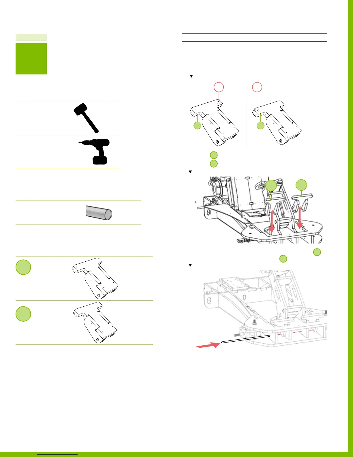
Part 5 Install the gas & brake pedals
INSTRUCTIONS
1. Each assembly has a long tab with a hole. The position of
the pedal is dictated by these holes. The holes should be
pointing towards the middle of the xed steering column.
Note the right and left pedals tabs, holes, and their position in the Assembly.
2. Position
5
on the right of the xed steering column.
3. Position
6
on the left of the xed steering column.
Note location and orientation of the assembly 5 & 6.
4. Insert the precision rod through the holes located in
5
and then through the holes located in
6
.
Note location of the precision rod.
5. Using a hammer, tap into place.
6. Test the alignment of each pedal assembly.
‒ Each pedal should be able to move freely and
independently (some drag is expected).
6 5
1
2
6
5
47
PlyFly Go‑Kart Instruction Guide • 2015 Release