150718 PLYFLY rev A_GoKart | Aug ust 7, 2 015 5 :08 PM
Chapter 10
3
PART
Recommended tools
DESCRIPTION REFERENCE
Electric Driver
Allen Wrench
or ratcheting Allen wrench
Required hardware
№ DESCRIPTION REFERENCE
1 Nylon Spacer
3/4” OD, 3/8” ID, 1‑1/4” L
P N 125 46
4 Flat Washer
5/16” ID, 7/8” OD
P N 12516
1
Short Shoulder Screw
3/8” D, 1” L, 5/16”‑18
P N 12513
1
Long Shoulder Screw
3/8” D, 2‑1/4” L, 5/16”‑18
P N 12514
Required assemblies
DESCRIPTION REFERENCE
1
Steering rack
Assembly
Parts 9‑12
3
Steering Column
Assembly
PARTS 19‑21
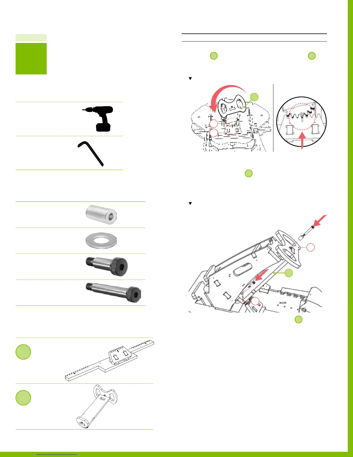
Part 3 Install the steering column assembly
INSTRUCTIONS
1. Position
3
, so that the gear aligns with those on
1
.
‒ Be sure the gear alignment marks located on
parts 20 & 12 line up.
Note-the orientation and alignment of the gear teeth
2. Insert the shoulder screws.
‒ Insert the short shoulder screw through the bushing
located on part 20 of
3
.
‒ Insert the long shoulder screw with the nylon spacer
through the tee nut located on part 21.
‒ Total 2 locations, 2 shoulder screws.
Note-the orientation of the bolt; be sure the head faces down
(toward the ground).
3. To secure, tighten both the shoulder screws
3
.
‒ Total 2 locations.
20
12
3
21
21
3
45
PlyFly Go‑Kart Instruction Guide • 2015 Release