150718 PL YFLY rev A_Frame | Aug us t 7, 20 15 5:0 6 P M
Assembling the frame
INSTRUCTIONS
1. To begin this assembly
‒ Start at Step 2 if you have a
SINGLE WHEEL KIT.
‒ Start at Step 4 if you have a
LIVE AXLE KIT.
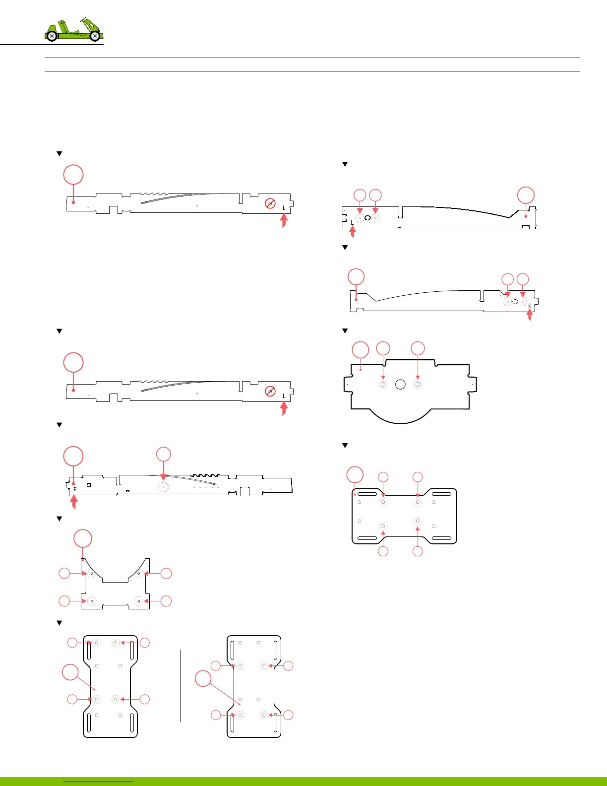
2. Press the bushing into part 40.
Note the location of the bushing on part 40. Install on the opposite side of the L.
3. Using a hammer, tap the bushing until the top is ush with
the wooden part.
4. Press the small tee nuts into
‒ Part 40‑41
‒ Part 49
‒ Part 50; be sure to follow installation pattern for the
correct engine model.
Note the location of the small tee nut on part 40; install on the same side of
the L.
Note the location of the small tee nut on part 41. Install on the same side of
the L.
Note the location of 4 small tee nuts on part 49.
Note the location of 4 small tee nuts on part 50
5. Press the large tee nuts into
‒ Part 42‑43
‒ Part 47
‒ Part 50; on the opposite side of the small tee nut
installation.
Note the location of 2 large tee nuts on part 42. Install on the same side of
the L.
Note the location of 2 large tee nuts on part 43. Install on the same side of
the L.
Note the location of 2 large tee nust on part 47.
Note the location of 4 large tee nuts on part 50. Install on opposing side of the
small tee nut installion on part 50.
6. Using a hammer, tap the tee nuts until the top is ush with
the wooden part.
‒ Parts 41‑43, 47, 49 & 50.
‒ Use 20 tee nuts; 10 small and 10 large.
‒ Total of 20 locations.
7. Screw in the llester head machine screws into the
tee nuts located parts 40 & 41.
‒ Tighten down until it stands ush with 3/8” protrusion.
40
40
1
41
49
1
2
3
4
2
1
4
3
2.5 HP
4.0 HP
2
1
4
3
50
50
42
1 2
43
1 2
47
1 2
50
1 2
3 4
32
9 Frame Assembly