150718 PLYFLY rev A_GoKart | Aug ust 7, 2 015 5 :08 PM
Chapter 10
9
PART
Recommended tools
DESCRIPTION REFERENCE
Dead blow Hammer
or mallet
Required hardware
№ DESCRIPTION REFERENCE
2 Fillister Head Screw
5/16”‑18, 3/4” L
PN 125 5 3
1 T‑Handle
Quick Release Pin
PN 125 42
1 Flag
Plyy ag
PN 125 3 5
Required assemblies
DESCRIPTION REFERENCE
4
Seat
Assembly
PARTS 22‑33
9
Frame
Assembly
PARTS 21‑28
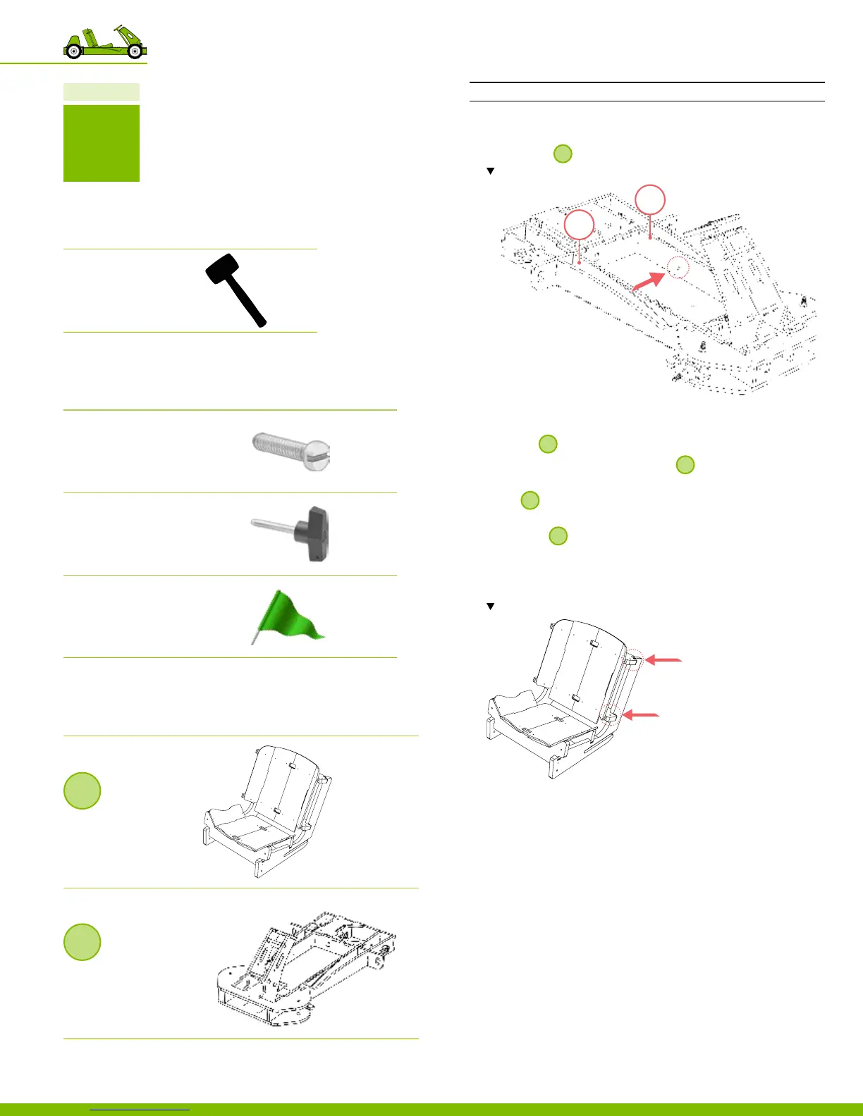
Part 9 Install the seat assembly
INSTRUCTIONS
1. Place the Fillister head screws into the parts 41 & 42
located on
9
.
Note the location of the Fillister head screws.
2. Secure the Fillister head screws to be ush with the
wooden surface of part 41.
3. Position
4
at the forward most position.
‒ Align the side slots located on
4
to the screw heads
located on parts 41 & 42.
4. Slide
4
backwards into position so that the pins slide all
the way through slots.
5. To secure
4
in place, insert the T‑handle, pin side,
through part 41 located on the right side of the go‑kart.
6. Insert the ag through holes located on the back right
side of Seat Assembly and the go‑kart frame.
Note the location of the ag holes.
41
42
58
10 Putting the go‑kart together