FLIR DM286 USER MANUAL Document Identifier: DM286-en-US_AA
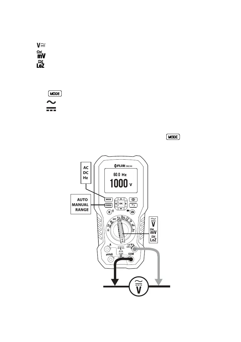
9.10 Voltage and Frequency Measurements
1. Set the function switch to one of the following positions. See Fig. 9.3.
•
For high voltage measurements
•
(milli-volts) for low voltage measurements.
•
for voltage measurements using the meter’s low input impedance mode.
The LoZ indicator will be displayed.
2. Insert the black probe lead into the negative COM terminal and the red probe lead
into the positive terminal.
3. Use the
button to select AC or DC measurements:
• The
indicator will be displayed for AC measurements.
• The
indicator will be displayed for DC measurements.
4. Connect the probe leads in parallel to the part under test.
5. Read the voltage value on the display.
6. The Frequency (Hz) of the measured voltage is shown on the smaller, secondary
display digits above the primary voltage reading. Press the
button to view
only the Frequency reading.
Fig. 9.3 Voltage and Frequency Measurements