FLIR DM286 USER MANUAL Document Identifier: DM286-en-US_AA
9.12 Resistance Measurements
Warning: Do not perform diode, resistance, or continuity tests before removing power
from capacitors and other devices under test during a measurement. Injury to persons
can occur.
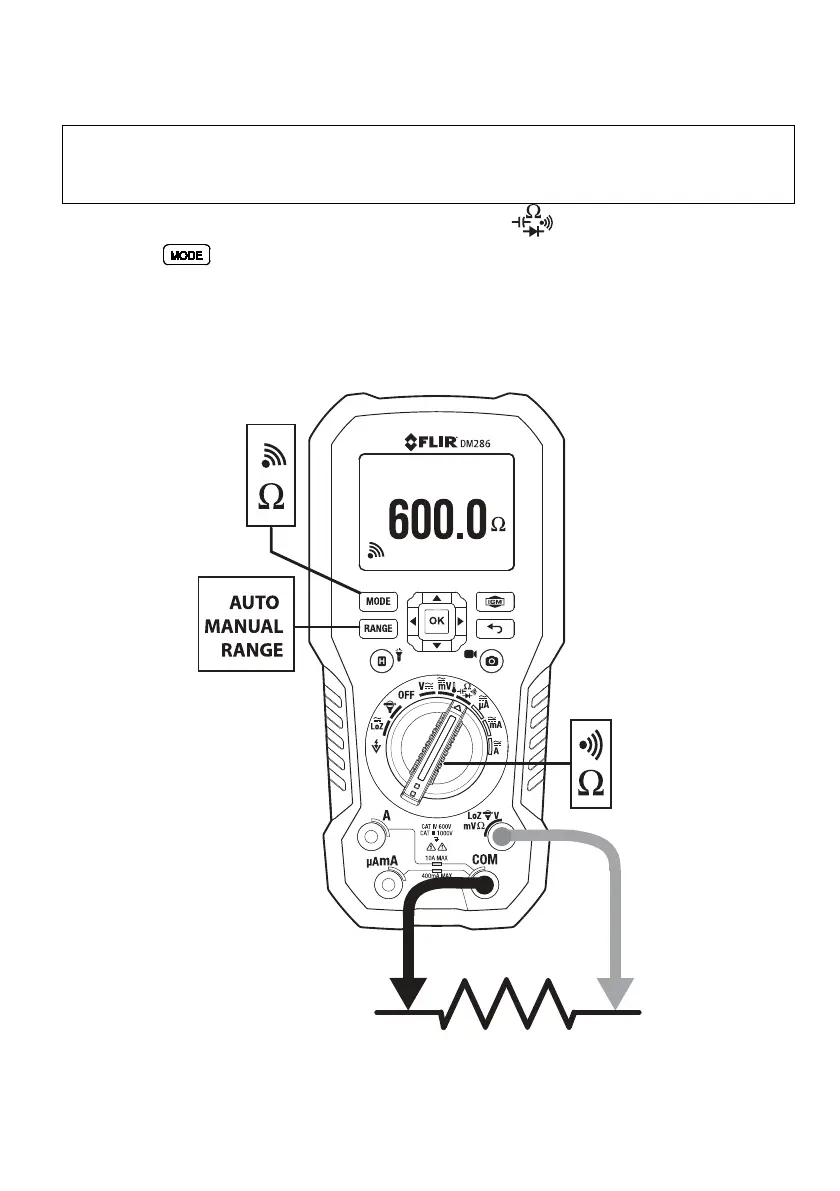
1. Refer to Fig. 9.5. Set the function switch to the position.
2. Use
to step to the Ω display if necessary.
3. Insert the black probe lead into the negative COM terminal and the red probe
lead into the positive Ω terminal.
4. Touch the tips of the probe across the circuit or component under test.
5. Read the resistance value on the display.
Fig. 9.5 Resistance and Continuity Measurements