FLIR DM286 USER MANUAL Document Identifier: DM286-en-US_AA
4. Meter Description and Reference
4.1 Meter Description
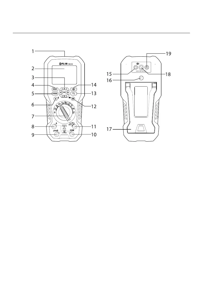
Fig. 4.1 Meter Description
1. Worklight and NCV detector area
2. LCD Display
3. Navigation/OK buttons
4. MODE button
5. RANGE button
6. Data Hold/Worklight button
7. Rotary Function switch. The switch border is color-coded to match the test lead input jacks
8. Positive (+) Probe Input for A (Current)
9. Positive (+) Probe Input for µA/mA (Current)
10. COM (-) Probe Input
11. Positive (+) Probe Input for all inputs except A and µA/mA
12. Image/Video capture button
13. Cancel/Return button
14. IGM (Thermal Imager) button
15. Digital Camera lens
16. Tripod mount
17. Tilt Stand/Battery compartment
18. Thermal Imaging lens
19. Laser pointer lens