FLIR DM286 USER MANUAL Document Identifier: DM286-en-US_AA
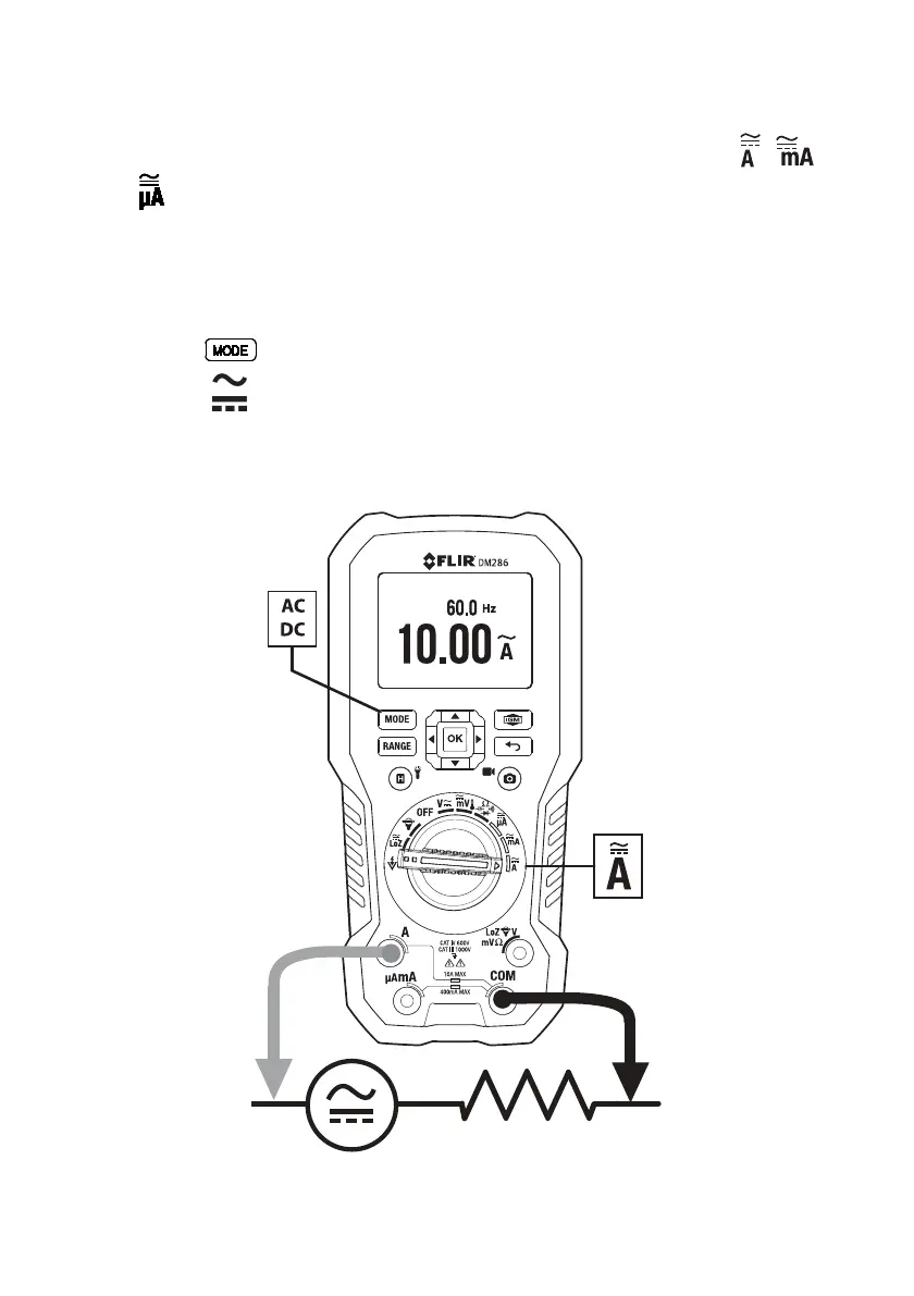
9.17.1 Test Lead Current Measurements (A, mA, and µA)
1. For test lead measurements (A, mA, and µA), set the function switch to the , or
position.
2. Insert the black probe lead into the negative COM terminal and the red probe lead into
one of the following positive terminals:
• A for high current measurements.
• mA for lower current measurements.
• µA for micro-amp measurements
3. Use the
button to select AC or DC measurement.
• The indicator will be displayed for AC measurements.
• The
indicator will be displayed for DC measurements.
4. Connect the probe leads in series with the part in accordance with Fig. 9.10 for ‘A’
measurements, Fig. 9.11 for mA measurements, or Fig. 9.12 for µA measurements.
5. Read the current and frequency values on the display.
Fig. 9.10 High Current ‘A’ Measurements