Victor Xu Page 23 12 Jan. 2011
Copyright 2011 © Shenzhen Runtianzhi Image Technology, Co., Ltd.
http://www.floradigital.com
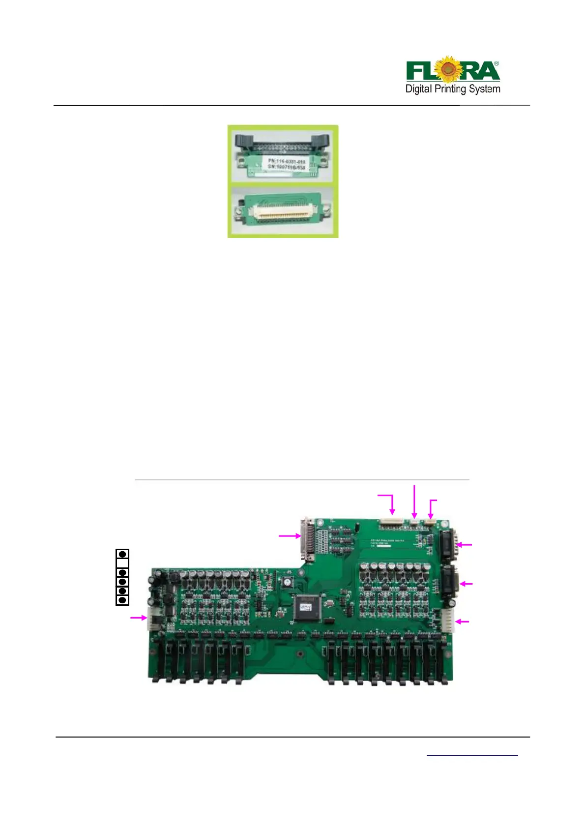
4.3.2 Print head Control Board
The image data is fetched by the Print Head Control Board from the USB_IF buffer through
the Image Data Cable (UCBJ10PHBJP1) and 100-pin JP1 AMP connector. The image is then
processed by the image data processor and dispatch to the print heads. The printheads fires the
ink depending on the binary status read by the Raster Reader which is sent to the print head
control board.
Likewise, the print head heating control is also integrated into the Print Head Control Board.
Thus, the print head temperature can be accessed from the Floraprint driver graphical user
interface or GUI.
The carriage displacement pulse signal is sent from the encoder reader to the print head
control board through PHBJ9ENR1 into J9 D-sub connector.
The secondary ink tank level sensor signal from the secondary ink tanks pass through cable
J2 and into the J2 connector of the print head control board. If the secondary ink tanks are full,
corresponding LED indicators will turn on near the J4 connector. The binary status for the
secondary ink tank level is then sent to the Servo Driver Board through cable SCBJ7PHBJ7. It is
then processed on the Servo Control Board to activate the ink pump motors.
The shutters of the UV lamps were also controlled from the Print Head Control Board.
JP1 to USB IF
J2 to ink level sensors
J3 No Use
J4 To Negative
Pressure Sensor
J7 to Servo
Control Board
J6 to Raster
strip reader
J5 UV Lamp
Shutter Control
J1 to Power
Source (15/24
Vdc)
No use
GND
24Vdc
15Vdc
15Vdc
GND
Print Head Connector Board