Victor Xu Page 53 12 Jan. 2011
Copyright 2011 © Shenzhen Runtianzhi Image Technology, Co., Ltd.
http://www.floradigital.com
5.5.3.5 Step Align
¾ On the printer tab select Step Align option then click send print as shown below.
Further below shows how the print out should look like. The Illustration shows
three different scenarios.
¾ The broken line was colored pink for the purpose of better understanding, the
horizontal lines are printed black in actual output. When you do step align the
first pass will print broken lines while the second pass will print the solid lines.
¾ Figure 1 shows the motor step value when the test was sent is higher than exact
value so we need to increase, by trial and error method you can get the correct
value.
Fi
ure 1 –Insufficient Feedin
Ste
Fi
ure 2 –Excessive Feedin
Ste
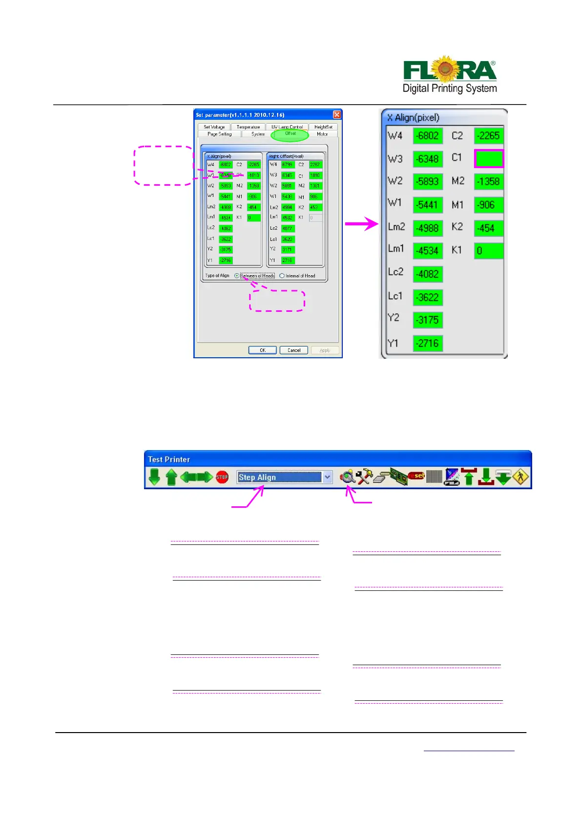
-1813
De
ault value
of C1 is -1810
-1810-3=-1813
Tick Between
of heads
Click to send print
ali
n
Select Step
lign