Victor Xu Page 48 12 Jan. 2011
Copyright 2011 © Shenzhen Runtianzhi Image Technology, Co., Ltd.
http://www.floradigital.com
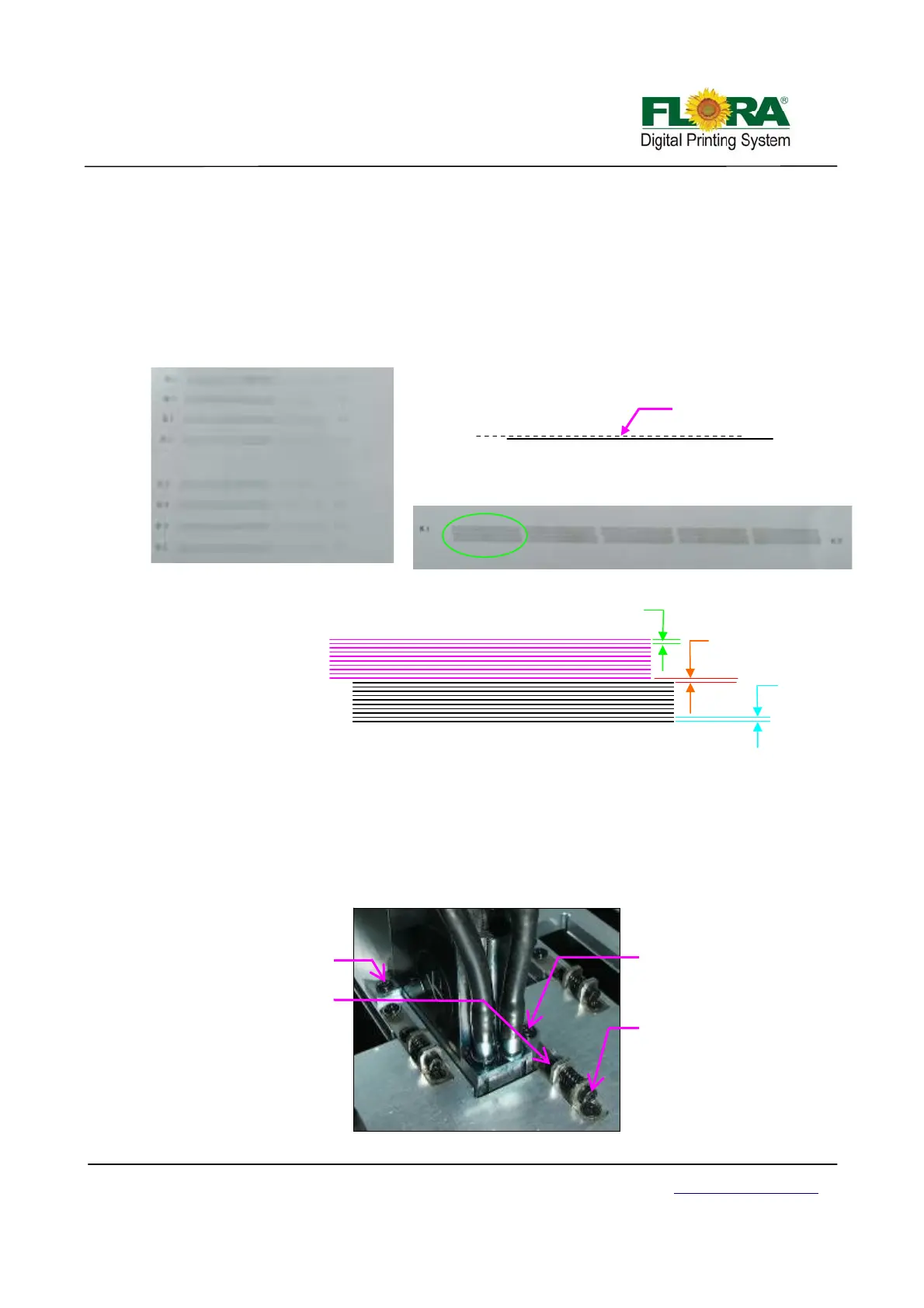
¾ Noticed there are sets of horizontal lines for K1 and K2. For the purpose of
identifying sets of horizontal lines, K1 horizontal lines are colored pink, and the
K2 is black though in actual print they are all printed black.
¾ The first sets of horizontal lines is a K1 single broken line and K2 solid line,
ignore the first 4 sets, select the rightmost set (with more horizontal lines) to get
more accurate alignment. First you must align K1 to K2. The gap between K1
and K2 horizontal lines must be the same as the spacing between all K1 or K2
horizontal lines. Please see Illustrations below.
¾ Once K1 and K2 print heads are aligned, tighten the two fixation screws properly.
Do Y-align to other print heads in such a way C1, M1,Y1,W1,Lm1,Lc1 and V1
will be aligned to K1 and C2,M2,Y2,W2,Lm2,Lc2 and V2 should align to K2. This
is applicable to PP2512VKMUV model only.
Note: For PP2512KMUV the V1 will be replaced by W3 while the V2 will be
replaced by W4 print heads when doing Y-align.
¾ Below shows how to do Y-alignment of the print heads.
K1
K2
This gap should
be the same as
gap K1and K2
Gap K1
Gap K2
Printed sample
Printed sample
K1 and K2 Y-align first set of Horizontal lines
K2
This set of line is for info only
Printhead
These screws should be
slightly tighten before
doing the Y-alignment
This screw must be tightened
before doing the Y-alignment
Turn this screw clockwise to pull the
print head forward and counter
clockwise to push back.