43B
Service Manual
7-12
7. Check TP151 (POS-A) and TP251 (POS-B) for about +1.1V (trace at mid-screen),
+0.4V (trace at top of screen), +1.8V (trace at bottom of screen).
If not correct check the PWM circuit (in the Digital Circuit).
8. Check TP152 (OFFSET-A) and TP252 (OFFSET-B) for about +1.1V.
9. Check TP303 (REFN) for -1.2V.
10. Check TP153 (DACTESTA) and TP253 (DACTESTB) for 0V. If TP153 is +1.7V,
the C-ASIC is in the reset state (200 mV/div fixed sensitivity); check SDAT and
SCLK, see step 15.
11. Check TP155 (MIDADCA) and TP255 (MIDADCB) for about +0.9V.
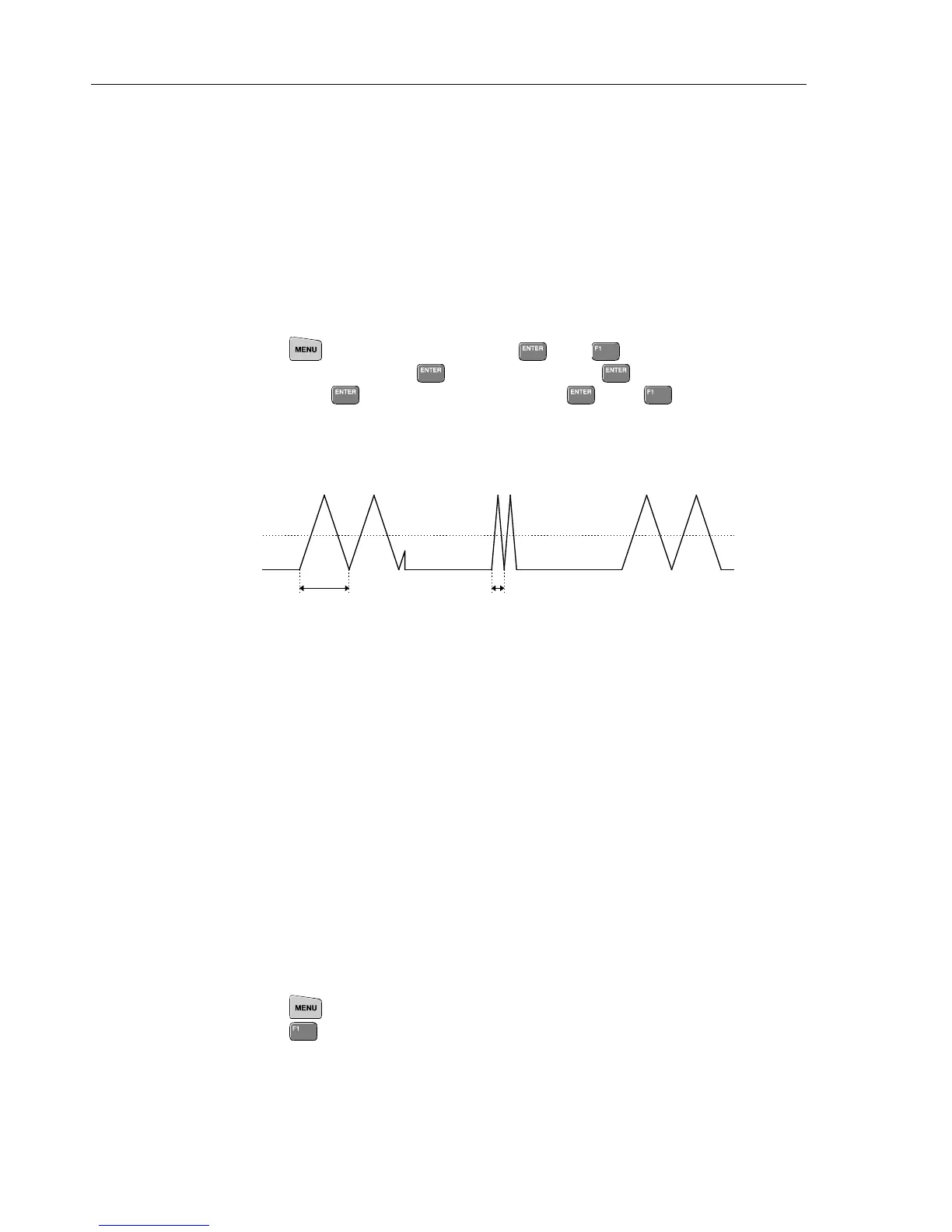
12. Select the Scope Normal mode for both input channels:
Press
, highlight SCOPE and press , press (SETUP), highlight INPUT
2 Coupling: XXX, press
, highlight
DC, press , highlight Time Base:
XXX, press
, highlight
NORMAL, press , press BACK.
Select a time base setting of 20 ms/d.
13. Check TP258 (TRACEROT supplied by T-ASIC N301) for the signals shown below
(typical example at 20 ms/div.).
+0.8V
-0.8V
≈
100 ms
≈
5 ms
If not correct check:
TP432 (RAMPCLK) for 3V, 200 ns pulses.
TP332 (RAMPCLK) for 0.6V, 200 ns pulses.
TP331 (RSTRAMP) for +3V pulses, with varying pulse with and repetition rate.
All pulses are supplied by D-ASIC-D471.
14. Check TP310 (REFATT) for alternating +1.2V and -1.2V pulses. The repetition
time depends on the time base, and is for example 9 s at 20 ms/div.
15. Check the SCLK and SDAT lines for +3.3V pulse bursts (C-ASIC pin 25 and 26).
16. Check TP437 (Sample clock) for a 5 MHz (time base ≥ 1 ms/div) or 25 MHz clock
signal (3.3V).
17. Check TP301 (REFADCT) for +1.62V, and TP302 (REFADCB) for +0.12V
18. Check the ADC supply voltages VDDAA ,VDDDA, VDDBB, VDDDB, and VDD0
for+3.3V
19. Check TP401 and TP451 for 0V.
7.5.7 Ohms and Capacitance Measurements
1. Press and select OHMS/CONTINUITY/CAPACITANCE.
Press
(Ohms).
Connect a current meter between Input 1 and the COM input. Select the various
Ohms ranges, and verify that the current approximately matches the values listed in

 Loading...


