43B
Service Manual
5-10
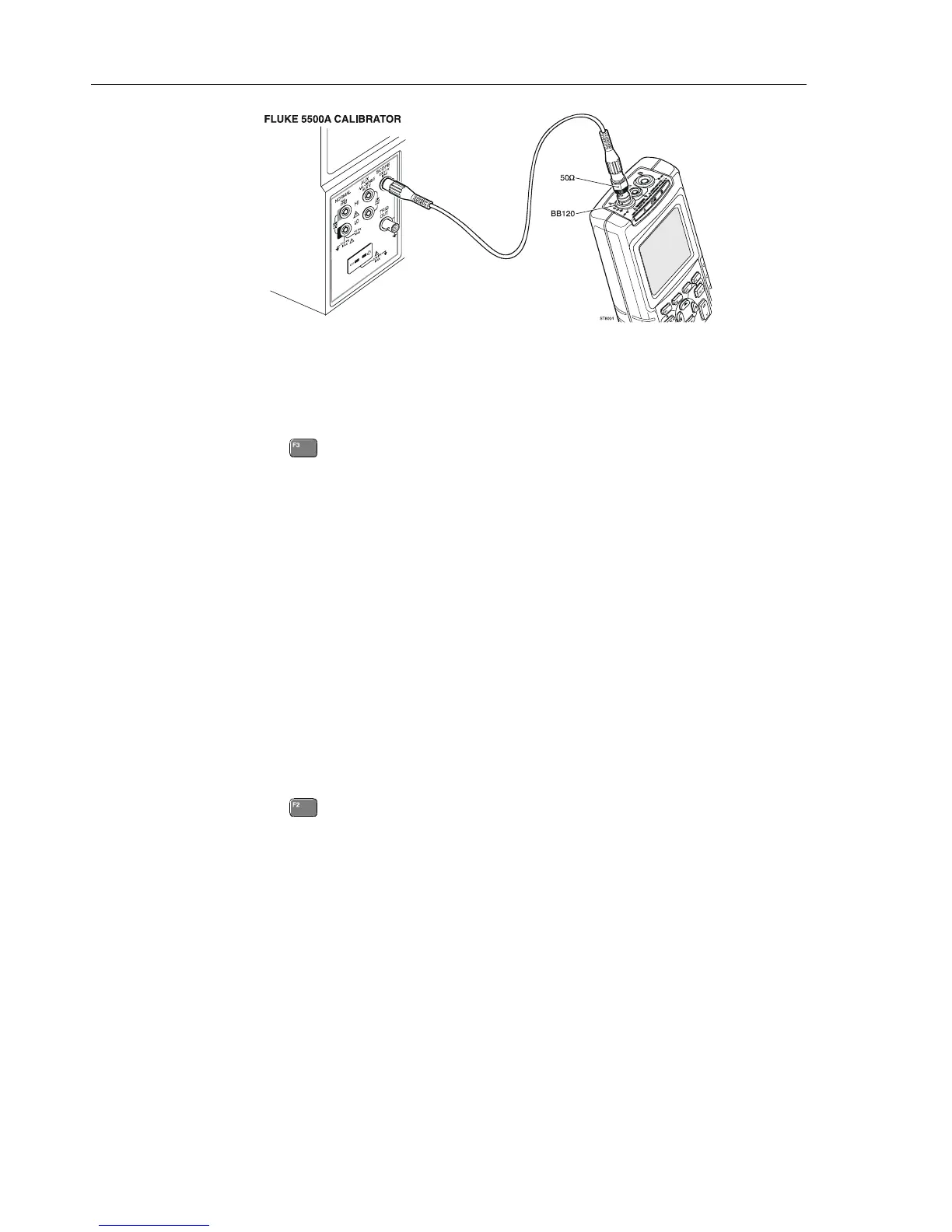
ST8004.WMF
Figure 5-4. 5500A Scope Output to Input 1
3. Set the 5500A to source a 1V, 1 MHz fast rising (rise time ≤ 1 ns) square wave
(SCOPE output, MODE edge).
4. Set the 5500A to operate (OPR).
5. Press
to start the calibration.
The Delta T gain, Trigger Delay (CL0720), and Pulse Adjust Input 1 (CL0640) will
be calibrated.
6. Wait until the display shows
Pulse Adj A (CL 0640):READY.
7. When you are finished, set the 5500A to Standby.
8. Continue at Section 5.6.3.
5.6.3 Gain DMM (Gain Volt)
Warning
Dangerous voltages will be present on the calibration source
and connection cables during the following steps. Ensure that
the calibrator is in standby mode before making any connection
between the calibrator and the test tool.
Proceed as follows to do the Gain DMM calibration.
1. Press
to select the first calibration step in Table 5-3.
2. Connect the test tool to the 5500A as shown in Figure 5-5.

 Loading...


