43B
Service Manual
7-14
7.5.9 Reference Voltages
1. Check:
a. TP306 for +3.3V, TP307 for +1.23V
If not correct check/replace V301, R307, C3112, P-ASIC N501.
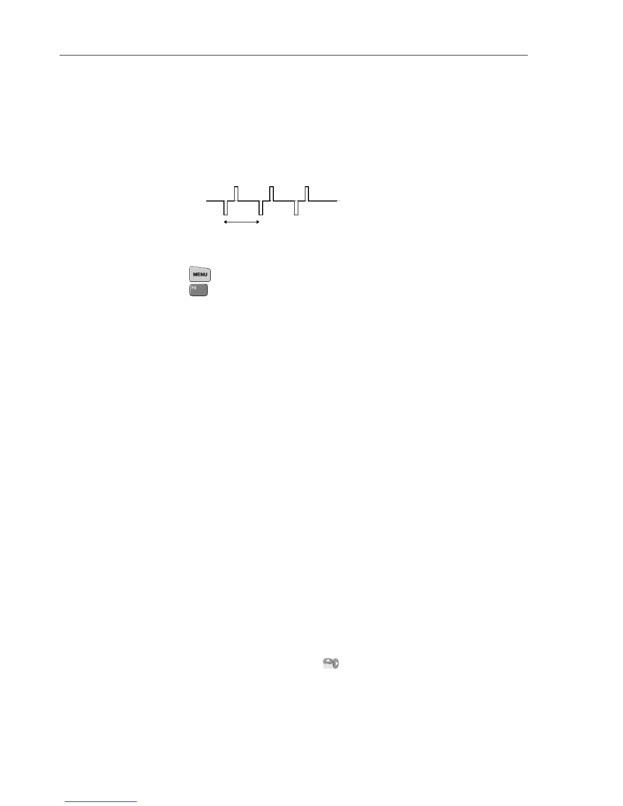
b. TP301 for +1.6V ; TP302 for +0.1V ; TP304 for +3.3V ;
TP310, see figure below (in ROLL mode TP310 is zero).
If not correct, check/replace REFERENCE GAIN circuit and T-ASIC N301.
+1.2V
-1.2V
≈
800 ms
TP310
7.5.10 Buzzer Circuit
1. Press and select OHMS/CONTINUITY/CAPACITANCE.
Press
(Continuity).
2. Short circuit Input 1 to COM. The buzzer is activated now.
3. Check TP496 for a 4 kHz, 0...3V square wave during beeping (+3 V if not activated).
4. Check TP495 for a 4 kHz +3...-30V square wave during beeping (TP495 is +3V if
the beeper is not activated).
7.5.11 Reset ROM Line (ROMRST)
1. Check TP487 for +3V (supplied by D471).
7.5.12 RAM Test
You can use the Microsoft Windows Terminal program to test the RAM. Proceed as
follows:
1. Connect the Test Tool to a PC via the Optical Interface Cable PM9080.
2. Start the Terminal program, and select the following Settings:
Terminal Emulation TTY (Generic)
Terminal Preferences Terminal Modes CR -> CR/LF
Line Wrap
Inbound
Local
Echo Outbound
Sound
Communications Baud Rate 9600
Data Bits 8
Stop Bits 1
Parity None
Flow Control Xon/Xoff
Connector COMn
3. Turn the test tool off. Keep the keys
pressed, and turn the test tool on again.
This will start up the mask software. You will hear a very weak beep now.

 Loading...


