43B
Service Manual
3-20
lead, or a BB120 shielded banana-to-BNC adapter, is inserted in Input 1 or Input 2, it
will short the two ground shield halves This can be detected by the D-ASIC.
Supply Voltages
The +5VA, +3V3A, and -3V3A supply voltages are supplied by the Fly Back Converter
on the POWER part. The voltages are present only if the test tool is turned on.
3.3.3 Trigger Circuit
The description refers to circuit diagram Figure 9-3. The trigger section is built up
around the T-ASIC OQ0257. It provides the following functions:
• Triggering: trigger source selection, trigger signal conditioning, and generation of
trigger information to be supplied to the D-ASIC.
• Current source for resistance and capacitance measurements.
• Voltage reference source: buffering and generation of reference voltages.
• AC/DC relay and Resistance/Capacitance (Ω/F) relay control.
Triggering
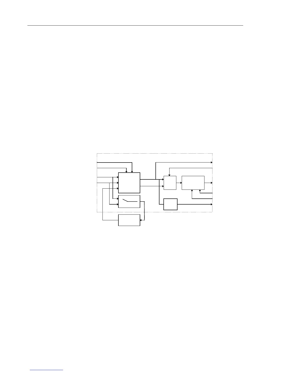
Figure 3-10 shows the block diagram of the T-ASIC trigger section.
synchronize
delta-t
TRIGGER ASIC OQ0257
trigger section
analog
trigger
path
TRIG A
TRIG B
TVSYNC
TRIGLEV1
TRIGLEV2
HOLDOFF
SMPCLK
LLTRIG
DUALTRIG
10
11
15
13
16
39
38
35
TRIGQUAL
select
logic
ALLTRIG
TRIGDT
42
34
High pass
filter
12
TVOUT
freq.
detect
29
DACTEST
Figure 3-10. T-ASIC Trigger Section Block Diagram
The analog trigger path uses the Input 1 (TRIG A) or Input 2 (TRIG B) signal for
triggering.
In the Transients mode the TRIG A or TRIG B signal is routed via a high pass filter
(TVOUT - TVSYNC). The High Pass Filter consists of C395 and R399.
The TRIG-A, TRIG-B, or TVSYNC signal, and two trigger level voltages TRIGLEV1
and TRIGLEV2, are supplied to the analog trigger part. The trigger level voltages are,
supplied by the PWM section on the Digital part (See Section 3.3.4). The TRIGLEV1
voltage is used for triggering on a negative slope of the Input 1/2 voltage. The
TRIGLEV2 voltage is used for triggering on a positive slope of the Input 1/2 voltage. As
the C-ASIC inverts the Input 1/2 voltage, the TRIGA, TRIGB slopes on the T-ASIC
input are inverted! From the selected trigger source signal and the used trigger level
voltages, the ALLTRIG and the DUALTRIG trigger signal are derived. The select logic
selects which one will be used by the synchronization/delta-T circuit to generate the final
trigger. There are three possibilities:

 Loading...


