Performance Verification
4.5 Input 1 and Input 2 Tests in the SCOPE MODE.
4
4-9
4.5.4 Input 2 Frequency Measurement Accuracy Test
Proceed as follows to test the Input 2 frequency measurement accuracy:
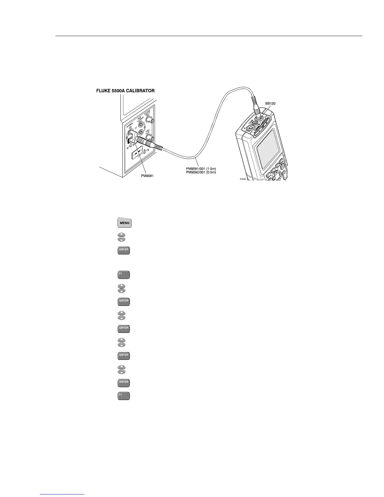
1. Connect the test tool to the 5500A as shown in Figure 4-3.
ST8588.wmf
Figure 4-3. Test Tool Input 2 to 5500A NORMAL output
2. Select the AUTO test tool setup:
• Press
to select the MENU.
• Press
till SCOPE is highlighted.
• Press
to select SCOPE mode
3. Select the following test tool setup:
• Press to select menu SCOPE SETUP.
• Press
to highlight Input 2 Reading
• Press
to go to Input 2 READING.
• Press
to highlight Hz.
• Press
to confirm; mark changes to ■.
• Press
to highlight Input 2 Coupling.
• Press
to select the Input 2 Coupling menu.
• Press
to highlight DC Coupling.
• Press
to confirm; mark changes to ■
• Press
to return to SCOPE.
4. Set the 5500A to source a sine wave of 600 mV, 15 kHz (NORMAL output, MODE
WAVE sine).
5. Observe the Input 2 main reading on the test tool and check the reading between 14.8
and 15.2 kHz.
6. When you are finished, set the 5500A to Standby.

 Loading...


