Calibration Adjustment
5.6 Final Calibration
5
5-9
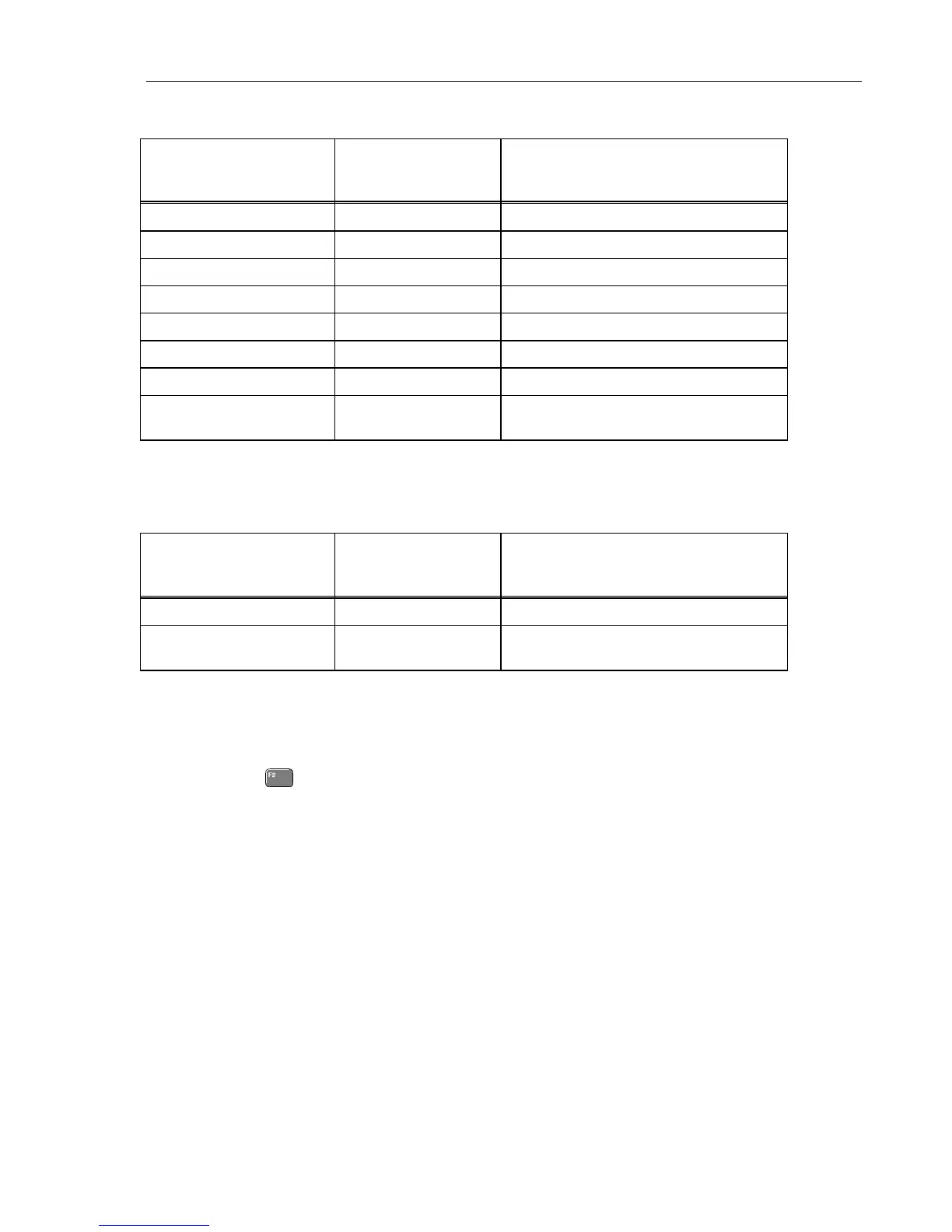
Table 5-1. HF Gain Calibration Points Fast
Cal step 5500A Setting
1)
(1 kHz, no 50 Ω!)
Test Tool Input Signal Requirements
1)
(1 kHz, t
rise
<100 ns, flatness after rising
edge: <0.5% after 200 ns)
HFG & FI A(B) (CL 0600) 10 mV 20 mV
HFG & FI A(B) (CL 0601) 25 mV 50 mV
HFG & FI A(B) (CL 0602) 50 mV 100 mV
HFG & FI A(B) (CL 0603) 100 mV 200 mV
HFG & FI A(B) (CL 0604) 250 mV 500 mV
HFG & FI A(B) (CL 0605) 500 mV 1 V
HFG & FI A(B) (CL 0606) 1 V 2 V
HFG & FI A(B) (CL 0607)
[HFG & FI A (CL 0608)]
2)
2.5 V 5 V
1)
As the 5500A output is not terminated with 50Ω, its output voltage is two times its set voltage
2)
After starting the first step in this table cell, these steps are done automatically.
Table 5-2. HF Gain Calibration Points Slow
Cal step 5500A Setting
(1 kHz, MODE wavegen,
WAVE square)
Test Tool Input Signal Requirements
(1 kHz square, t
rise
<2 µs,
flatness after rising edge: <0.5% after 4 µs)
HF-Gain A(B) (CL 0609) 25 V 25 V
HF-Gain A (CL 0612),
[HF-Gain A (CL 0615)
1)
50 V 50 V
1)
After starting the first step in this table cell, these steps are done automatically.
5.6.2 Delta T Gain, Trigger Delay Time & Pulse Adjust Input 1
Proceed as follows to do the calibrations:
1. Press
to select calibration step Delta T (CL 0700):IDLE
2. Connect the test tool to the 5500A as shown in Figure 5-4.

 Loading...


