Circuit Diagrams
9.1 Introduction
9
9-3
9.1 Introduction
This chapter contains all circuit diagrams and PCA drawings of the test tool. There are
no serviceable parts on the LCD unit. Therefore no circuit diagrams and drawings of the
LCD unit are provided.
Referring signals from one place to another in the circuit diagrams is done in the
following way:
A
B
C
1 2 3 4 5
A
B
C
1 2 3 4 5
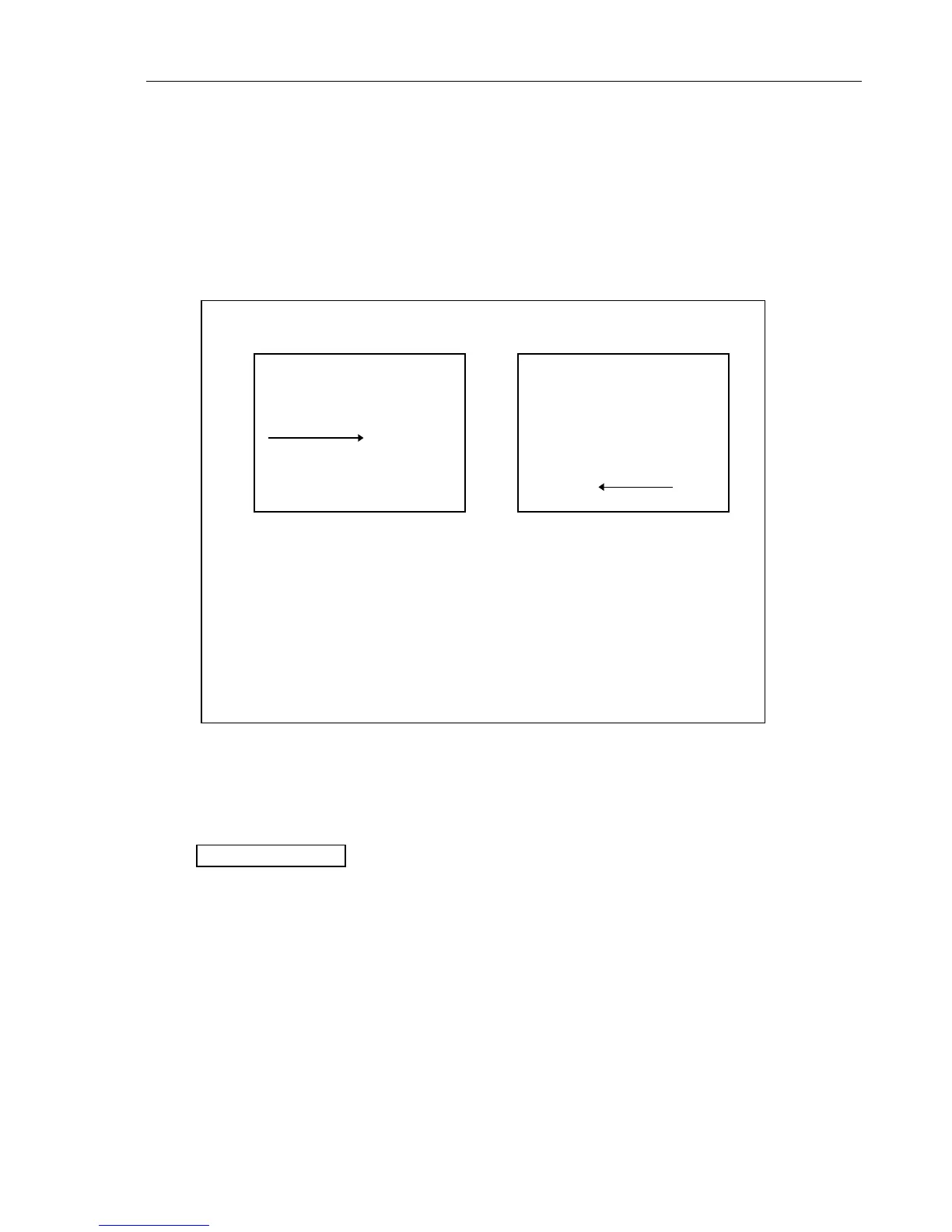
Figure 9.1 Circuit Diagram 1 Figure 9.5 Circuit diagram 5
[5, C2]
[1,B3]
SIGNAL
SIGNAL
The line SIGNAL on circuit diagram 1, location B3 [1,B3], is connecte
to the line SIGNAL on circuit diagram 5, location C2 [5,C2].
If the signal is referred to a location on the same circuit diagram, the
circuit diagram number is omitted.
9.2 Schematic Diagrams
The tables below show where to find the parts on the Main PCA circuit diagrams and
assembly drawings. Separate tables are created for the Main PCA side 1 and side 2
assembly drawing.
B402 C4 4, J10
indicates that part B402 can be found in:
location C4 on the Main PCA side 1 drawing
circuit diagram part 4, location J10.

 Loading...


