43B
Service Manual
5-14
ST8002.WMF
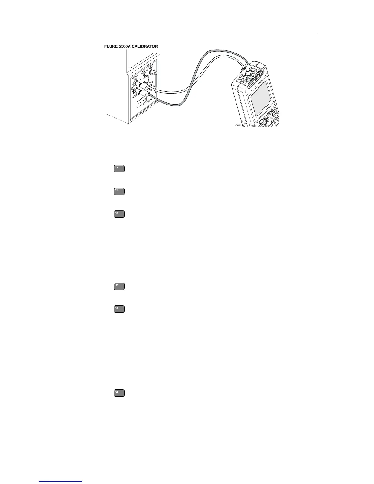
Figure 5-8. Capacitance Gain Calibration Input Connections
3. Set the 5500A to supply 250 mV DC.
4. Set the 5500A to operate (OPR).
5. Press to start the calibration.
6. Wait until the display shows
Cap. Low (CL 0900):READY.
7. Press
to select calibration adjustment step Cap. High (CL 0910):IDLE
8. Set the 5500A to supply 50 mV DC.
9. Press
to start the calibration.
10. Wait until the display shows
Cap High (CL 910):READY.
11. Set the 5500A to Standby.
12. Continue at Section 5.6.7.
5.6.7 Capacitance Clamp & Zero
Proceed as follows to do the Capacitance Clamp Voltage & Zero calibration:
1. Press
to select calibration adjustment step Cap. Clamp (CL 0940):IDLE
2. Remove any input connection from the test tool (open inputs).
3. Press
to start the calibration.
The capacitance measurement clamp voltage
Cap. Clamp (CL 0940), and the zero of
the capacitance ranges
Cap. Zero (CL 0950)... Cap. Zero (CL 0953) will be calibrated
now.
4. Wait until the display shows
Cap. Zero (CL 0953): READY.
5. Continue at Section 5.6.8.
5.6.8 Capacitance Gain
Proceed as follows to do the Capacitance Gain calibration:
1. Press
to select calibration adjustment step Cap. Gain (CL 0960):IDLE
2. Connect the test tool to the 5500A as shown in Figure 5-8.
3. Set the 5500A to 500 nF.

 Loading...


