Corrective Maintenance
7.5 Miscellaneous Functions
7
7-13
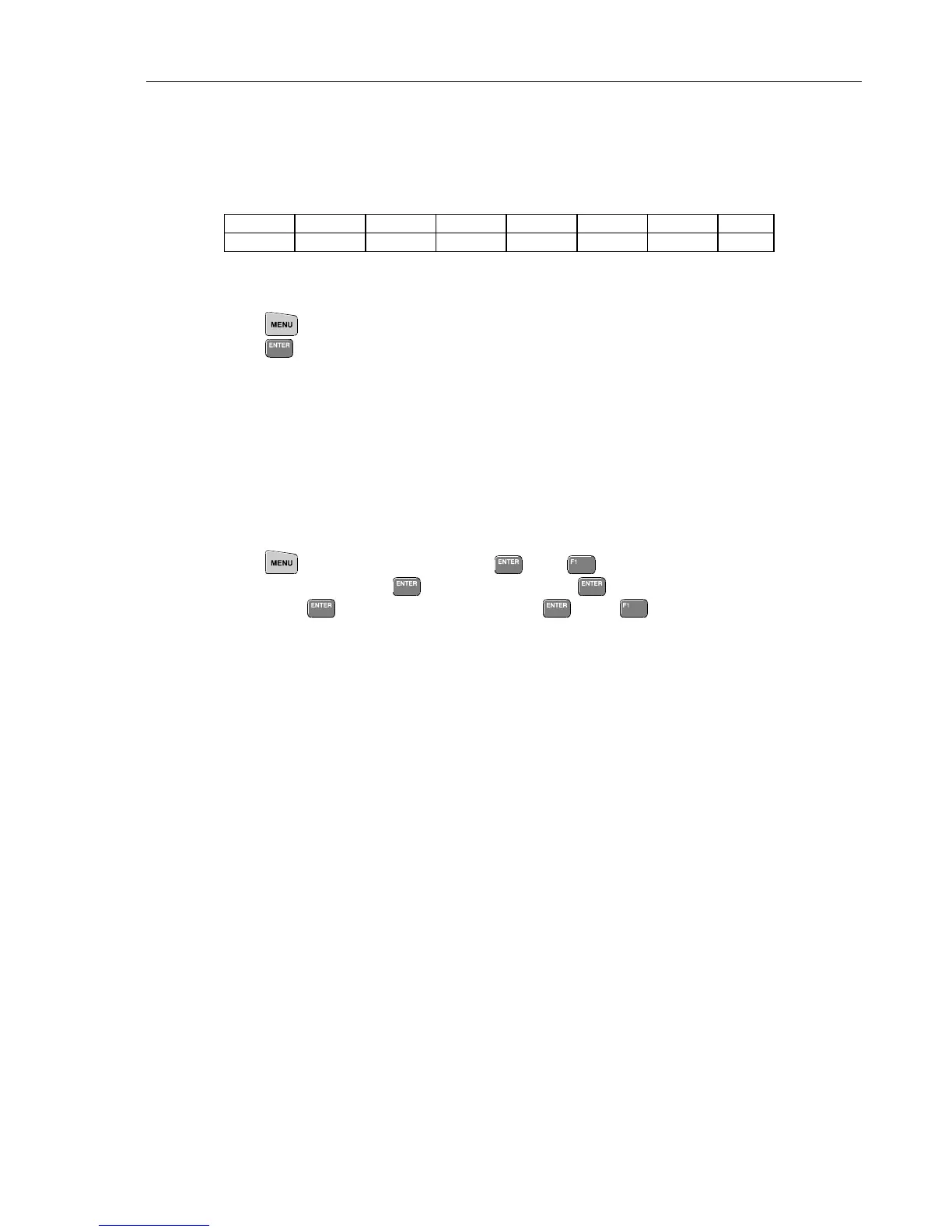
the table below.
If not correct, the protection circuit or the current source in the T-ASIC (N301) may
be defective.
If the current is correct, and the Volt function is correct (so ADC is correct), then the
Ohms part in the C-ASIC is defective: replace N101.
Range 50Ω
1)
500Ω 5 kΩ 50 kΩ 500 kΩ 5 MΩ 30 MΩ
Current 500 µA 500 µA 50 µA5 µA0.5 µA 50 nA 50 nA
1)
The 50Ω range is only available in the Continuity measurement function.
The current in the Diode measurement function must be 500 µA.
2. Press
and select OHMS/CONTINUITY/CAPACITANCE.
Press
(Capacitance).
Verify TP156 for +3.3 ... 0V pulses (repetition rate 100...200 ms):
Zero scale (open input): pulse width approximately 30 µs.
Full scale (for example 500 nF): pulse width approximately 25 ms.
If not correct, most probably the C-ASIC N101 is defective.
If correct continue at 7.5.8 Trigger functions (pulse width is measured via the
T-ASIC).
7.5.8 Trigger Functions
1. Select the Scope Normal mode for both input channels:
Press
, highlight SCOPE and press , press (SETUP), highlight INPUT
2 Coupling: XXX, press
, highlight
DC, press , highlight Time Base:
XXX, press
, highlight
NORMAL, press , press BACK.
2. Supply a 1 kHz sine wave of +/- 3 divisions to Input 1, and Input 2.
3. Check:
a. TP156, TP256 for a 600 mV (6 div. x 100 mV/div), 1 kHz, sine wave; the DC
level depends on the trace position. The sine wave is interrupted now and then
to do a reference measurement.
If not correct, C-ASIC N101/N102 is probably defective.
b. TP321, TP322 for 1.1...1.9V DC (move the trigger level from top to bottom).
If not correct check the PWM circuit, see 7.5.8.
c. TP311for a 0...+3.3V, 1 kHz square wave when the trigger level is at the middle
of the trace). Change the trigger level, and verify that the duty cycle of the
square wave changes. If not correct T-ASIC N301 may be defective.
d. TP433 for 0...+3.3V pulses. Pulse width:
4...10 µs for time base 2 µs/div and faster;
>40 µs for time base 5 µs/div and slower; pulse width increases with time base.
e. TP336 for +0.6...0V pulses, TP436 for +3.3...0V pulses; the pulse width is about
40 µs...10 ms.
If not correct, check the RANDOMIZE circuit, see 7.5.15.
f. TP437 (SMPCLK) for a 5 MHz (time base ≥ 10 ms/div) or 25 MHz (time base
< 1 ms/div) clock signal (3.3V). Check SMPCLK on both sides of R339.

 Loading...


