43B
Service Manual
5-8
5.6.1 HF Gain Input 1.
Proceed as follows to do the HF Gain Input 1&2 calibration:
1. Press
to select the first calibration step in Table 5-1 ( HFG & FI AB (CL 0600): )
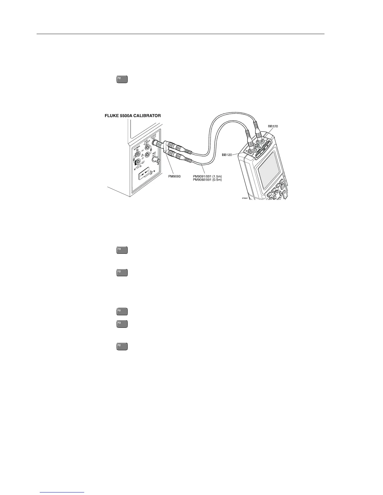
2. Connect the test tool to the 5500A as shown in Figure 5-3. Do NOT use a 50Ω
termination!
ST8097.WMF
Figure 5-3. HF Gain Calibration Input Connections
3. Set the 5500A to source a 1 kHz fast rising edge square wave (Output SCOPE,
MODE edge) to the first calibration point in Table 5-1.
4. Set the 5500A in operate (OPR).
5. Press
to start the calibration.
6. Wait until the display shows calibration status
READY .
7. Press
to select the next calibration step, set the 5500A to the next calibration
point, and start the calibration. Continue through all calibration points in Table 5-1.
8. Set the 5500A to source a 1 kHz square wave (Output SCOPE, MODE wavegen,
WAVE square), to the first calibration point in Table 5-2.
9. Press
to select the first step in Table 5-2.
10. Press
to start the calibration.
11. Wait until the display shows calibration status
READY.
12. Press
to select the next calibration step, set the 5500A to the next calibration
point, and start the calibration. Continue through all calibration points Table 5-2.
13. When you are finished, set the 5500A to Standby.
14. Continue at Section 5.6.2.

 Loading...


