iii
List of figures
Contents
List of gures
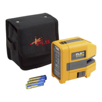
Figure 2-1. Items included with the Product ......................................................................6
Figure 3-1. Laser safety warning .......................................................................................7
Figure 4-1. The Product at a glance ................................................................................13
Figure 4-2. Charging the non-removable rechargeable battery.......................................16
Figure 4-3. Dismounting the charger plug .......................................................................17
Figure 4-4. Parts of the sensor ........................................................................................19
Figure 4-5. Parts of the prism ..........................................................................................20
Figure 4-6. Standard and optional brackets ....................................................................21
Figure 4-7. Wireless module ON/OFF switch ..................................................................23
Figure 6-1. Mounting components across the coupling ...................................................39
Figure 6-2. Laser dot centered on prism dust cap ...........................................................41
Figure 6-3. Centering the reected laser beam using
the thumbwheel and the yellow beam adjustment knob ..................................................44
Figure 7-1. Mounting the bracket step-by-step ................................................................49
Figure 7-2. Mounting wireless module and sensor ..........................................................51
Figure 7-3. Mounting and fastening prism .......................................................................51
Figure 7-4. Centering prism knob for maximum adjustment............................................52
Figure 7-5. Inserting sensor cable into the alignment tool ...............................................53
Figure 7-6. Machine dimensions to be entered ...............................................................55
Figure 7-7. Distance marking on the sensor and prism ...................................................55
Figure 7-8. Distance marking on the sensor....................................................................57
Figure 7-9. Horizontal and vertical adjustment of the laser beam ...................................65
Figure 7-10. Tolerance bar .............................................................................................72
Figure 7-11. Saving measurement report as PDF on a memory stick .............................85
Figure 7-12. Printing measurement report from Product directly to desired printer ........88
Figure 7-13. Parallel and angular soft foot ......................................................................91
Figure 7-14. Diagnosis of parallel and angular soft foot ..................................................99
Figure 9-1. Typical vertical machine conguration ........................................................107
Figure 9-2. Numbering the shaft ....................................................................................108
Figure 9-3. Numbering the housing ...............................................................................109
Figure 10-1. Replacing the wireless module cable with the sensor cable .....................121
Figure 10-2. Fastening the sensor cable .......................................................................122
Figure 10-3. Memory stick connected to the Product using the ‘short’ USB cable ........127