67
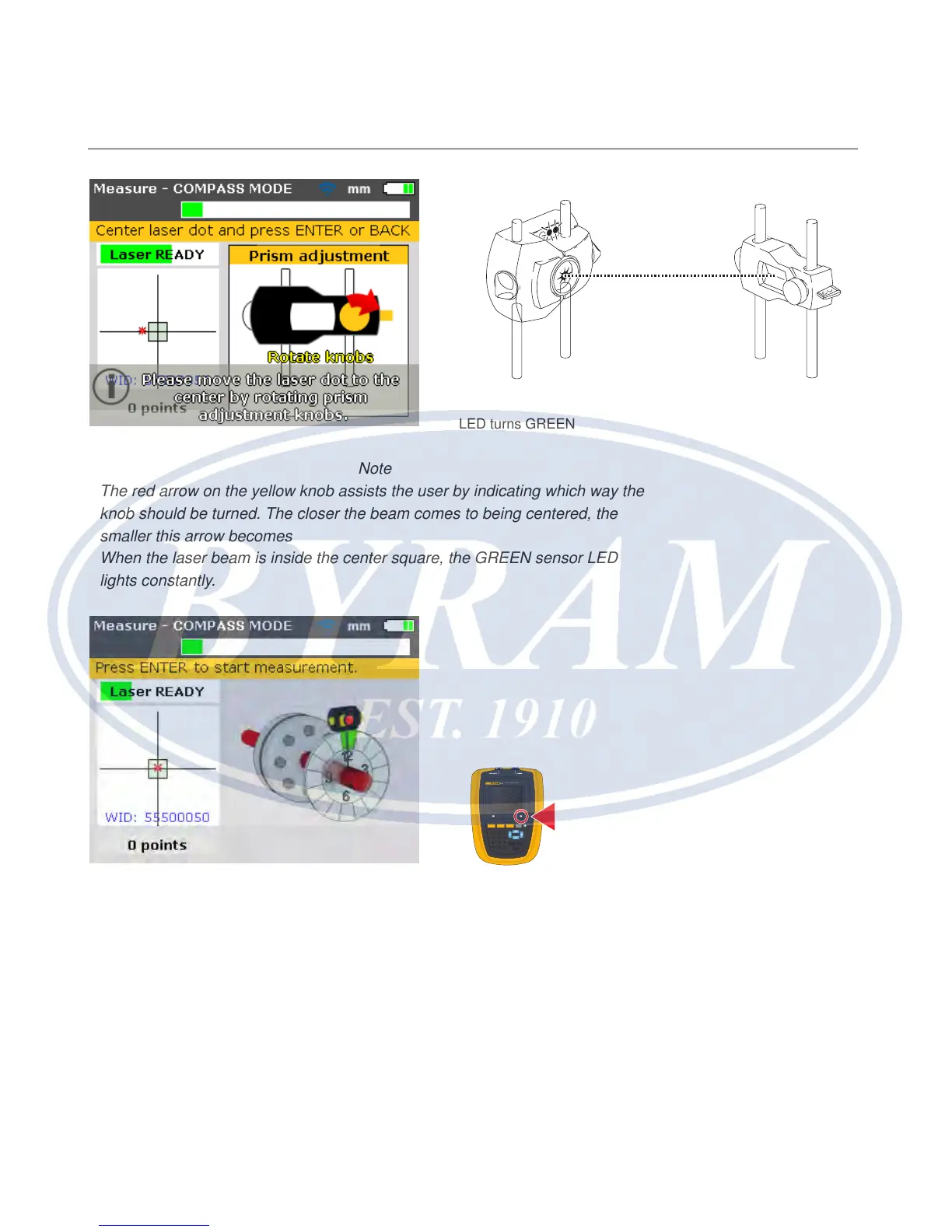
Note
The red arrow on the yellow knob assists the user by indicating which way the
knob should be turned. The closer the beam comes to being centered, the
smaller this arrow becomes
When the laser beam is inside the center square, the GREEN sensor LED
lights constantly.
Note
The beam does not have to be exactly at the center of the crosshair, as this
will not affect measurement accuracy. However, maximum range for measure-
ment is available when the beam is well centered.
Note
Once centered, the sensor and prism must not be touched, as any movement
during measurement will be interpreted as misalignment. These components
may however be moved when extending the measurement range.
GREEN sensor LED blinks slowly and the Product’s RIGHT
LED turns GREEN
830
LASER ALIGNMENT TOOL
SETUP MEASURE
DIAGNOSE MENU
CLEARENTER
BACK
1
2
ABC
3
DEF
4
GHI
5
JKL
6
MNO
7
PQRS
8
TUV
9
WXYZ
+
-
0
space
.
/
.
The RIGHT LED turns
BLUE
Horizontal shaft alignment
Laser beam adjustment