6 Chapter 1 DaqPRO
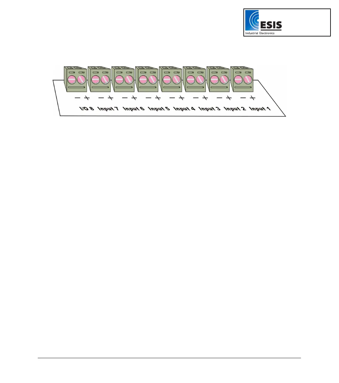
Connect the sensor to the terminal block at the top of DaqPRO:
Figure 2: DaqPRO’s inputs block terminal
Sensors must be added successively, starting with input–1. If a single sensor is used it must be
connected to Input–1. If two sensors are used, they must be connected to Input-1 and Input-2 and so on.
Alarm Output
I/O–8 (Input/Output–8) serves either as an input or as alarm output.
Polarity
Current, voltage, thermocouples and user defined sensors have distinct polarity. Be careful to connect
them in the right polarity.
Frequency/Pulse Counter
Connect the signal wires to I/O–8 screw terminals, and select Frequency or Pulse counter for Input 1
from the Setup menu. Inputs 2 to 7 are still available for other sensors.
The Frequency/pulse counter is optically isolated from the internal circuitry and can simultaneously
measure a signal source, together with another input.
3-wire PT 100
You have to use two inputs to connect a 3 wire PT 100. You can connect one 3-wire PT 100 to input–1
and input–5, and/or inputs 2 and 6, and/or inputs 3 and 7 and/or inputs 4 and 8.
Connect the single wire to the plus (+) terminal of the first input and the common end wires to the minus
(-) terminals of both the inputs.
www.esis.com.au
Ph 02 9481 7420
Fax 02 9481 7267
esis.enq@esis.com.au