8 Chapter 1 DaqPRO
1.1.5. Alarms
Users can define minimum and maximum alarm levels for each input individually.
DaqPRO places a small alarm icon
next to the corresponding input readings and can switch alarm
output if either level is breached.
To display alarm warnings in real-time DaqPRO must be in numeric display mode (see page
14).
To learn how to enter alarm levels and to activate alarm output, see section
2.5.1.2 on page 49.
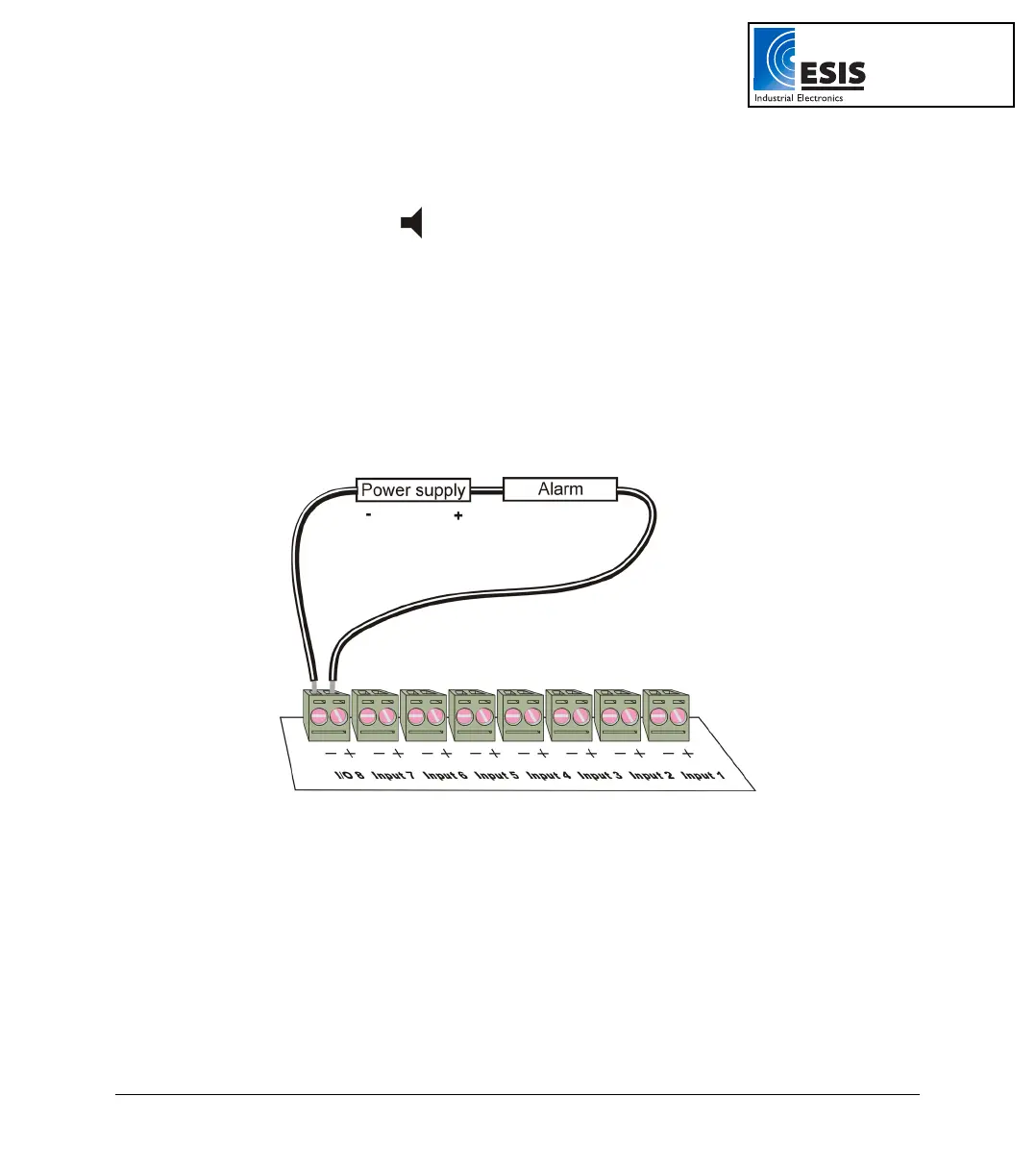
1.1.6. Alarm Output
DaqPRO can trigger an external event (e.g. sound alarm, warning light or oven).
Connect the external current loop to the screw terminals of I/O–8. Be careful to connect the external
power supply in the right polarity (see
Figure 4 below).
Figure 4: Connecting external alarm device
The alarm output is analogous to electrical switch. In OFF position the terminals of I/O–8 are
disconnected. In ON position they are shortened.
If an alarm output is selected this input/output is set to OFF position. When any active alarm level is
exceeded the output is set to ON. All active alarms must be false to reset the output to OFF position.
The maximum switch load is 50mA, 5V. The output is protected by 50mA reset-able fuse. For higher
loads use a relay.
To learn how to enter alarm levels and to activate alarm output, refer to section
2.5.1.2 on page 49.
www.esis.com.au
Ph 02 9481 7420
Fax 02 9481 7267
esis.enq@esis.com.au