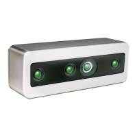
FRAMOS Industrial Depth Camera D400e Series - User Manual
Version 1.6.0
from 2021-10-15 15 of 64
3.5 Inertial Measurement Unit
Inertial Measurement Unit (IMU) contains sensors which allow measurement of both directional
movement and rotation. FRAMOS D400e depth cameras generate and transmit the gyro and
accelerometer samples independently, as the inertial sensors exhibit different FPS rates
(200/400Hz for gyro, 63/250Hz for accelerometer).
Accelerometer Sample Rate
1
Table 12 – IMU Specifications
NOTES:
1. The sample rate may differ from the absolute specified sample rate by ±5%. It is advised to rely
on the sample timestamp.
2. The sample rate may differ from the absolute specified sample rate by ±0.3%.
3.6 Image Signal Processor
The color sensor data is sent to an Image Signal processor (ISP) for a color image quality
enhancement. The enhanced image is sent to the onboard SoC for further processing.
Interface to Color Sensor
Table 13 – ISP Properties
3.7 FRAMOS D4 Visual Processing Board
FRAMOS D4 Visual Processing Board with integrated Intel® RealSense™ Vision Processor D4 for
depth calculation, provides a Gigabit Ethernet interface, Power over Ethernet (PoE) and additional
GPIOs for external triggering or user output.
For a module variant, ethernet, power supply and GPIOs can be connected directly to the board
without soldering via wire to board connectors (see Chapter 5.2).
FRAMOS D4 Visual Processing Board Key Components
System on Chip (SoC)
Processing unit that implements the control and
image data processing, external triggering and data
link layer of the Ethernet