FRAMOS Industrial Depth Camera D400e Series - User Manual
Version 1.6.0
from 2021-10-15 21 of 64
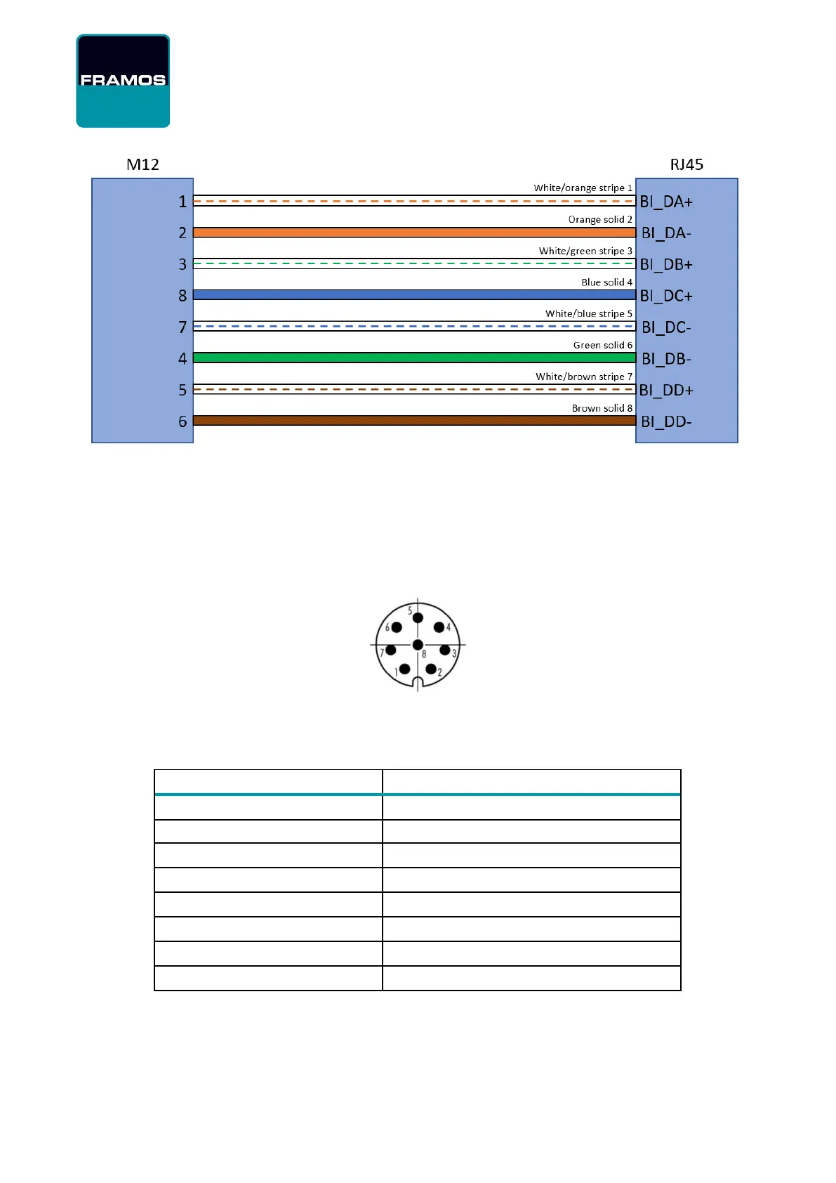
Figure 2 – Example of connecting M12 to RJ45, T568B termination
4.3.2 Power M8 connector, A-Coded, Male
Beside the Ethernet interface for communication and data transmission, FRAMOS D400e series
cameras are equipped with M8 connector providing I/O-interface and power input.
Figure 3 – M8 Connector PIN Layout
Via this interface cameras provide access to opto-isolated input and opto-isolated output.
DC Power supply, 12-24V DC (+/- 10%)
GND for opto isolated I/O
Table 19 – M8 Connector PIN Layout and Description