FRAMOS Industrial Depth Camera D400e Series - User Manual
Version 1.6.0
from 2021-10-15 37 of 64
Mounting and Deployment
7.1 Camera Mounting
D400e cameras are designed to support mounting on the back side of the housing. The internal
structure of the device is designed to dissipate most of the generated heat through this part of
camera housing. Therefore, it is recommended to use a holder or stand which will ensure good
mechanical stability of the camera but also act as a thermal drain. For this purpose, metal parts with
high thermal conductivity and which are physically connected to a large part of the camera back
side, are recommended. Please avoid materials like plastic, rubber or similar materials with high
thermal resistance.
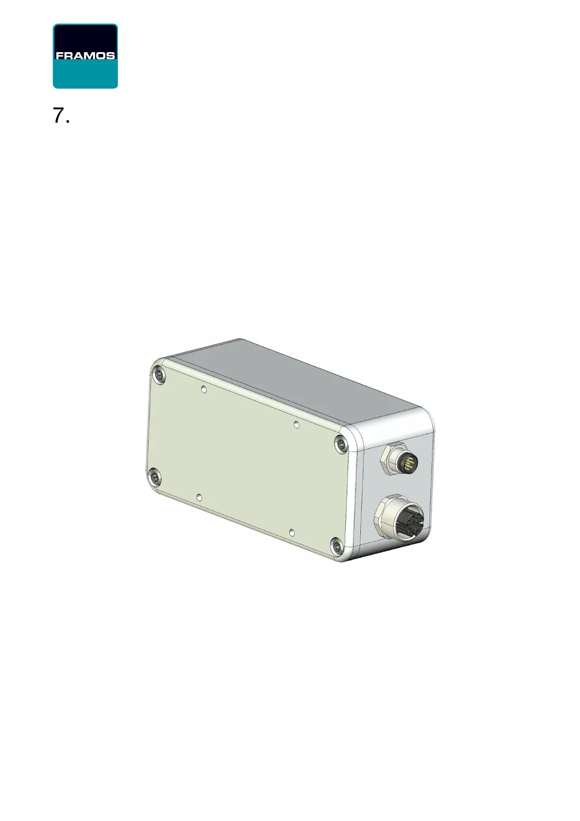
On the back side of the D415e/D435e camera body, four M3 thread holes are available for
mounting. Since the housing is made of aluminum and M3 thread holes depth is 3.2mm, care is
required when tightening the screws to avoid thread damage. Applied tightening torque should not
exceed 100 cNm for these screws.
Figure 19 – D400e Series Camera Body Back Side
The D455e camera features four robust M4 thread holes for mounting, with stainless steel thread
inserts and maximum insertion depth of 5mm. Applied tightening torque for mounting screws should
not exceed 100 cNm, to avoid thread damage.
The camera is constructed for operation in industrial environments and can be used with moving
objects. For this purpose, it is tested and compliant according to: EN 60068-2-6, EN 60068-2-64
and EN 60068-2-27 norms. However, stronger shock and vibration can lead to damage of sensitive
optical and electronic components inside the camera. Dropping the camera or colliding it with any
surface can lead to severe damage.