FRAMOS Industrial Depth Camera D400e Series - User Manual
Version 1.6.0
from 2021-10-15 20 of 64
4.3 Physical Interfaces
FRAMOS D400e series cameras are equipped with two physical interfaces:
M12 Ethernet connector for data interface
M8 Power connector for power and I/O interfaces
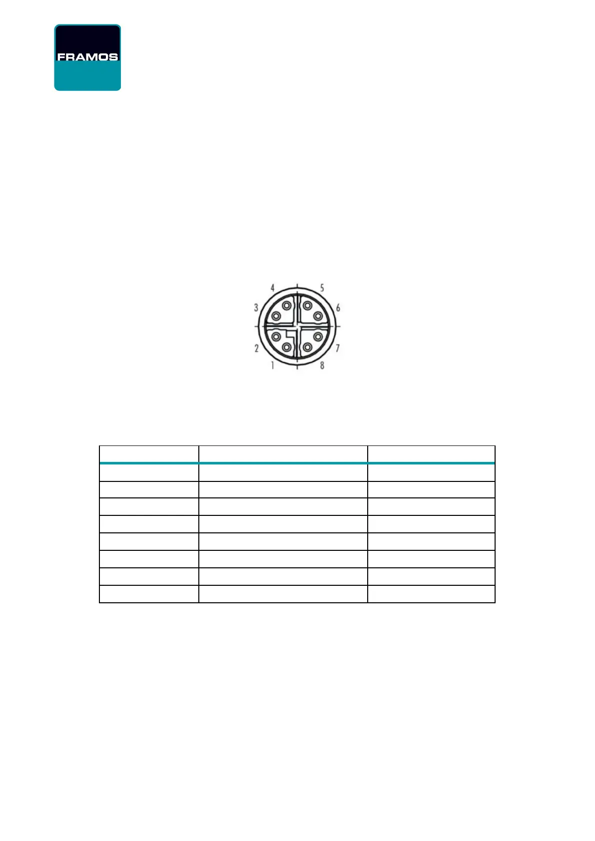
4.3.1 Ethernet M12 connector, X-Coded, Female
The Ethernet interface provides configuration access to the camera and is also used for image data
transmission.
Figure 1 – M12 Connector PIN Layout
The M12 connector is a circular connector, pins assigned like shown in Table 18.
Ethernet 1000BaseT, 802.3 compliant, ANSI/TIA-568 T568B termination
1 (BI_DA+, White/orange stripe)
3 (BI_DB+, White/green stripe)
7 (BI_DD+, White/brown stripe)
5 (BI_DC-, White/blue stripe)
Table 18 – M12 Connector PIN Layout and Description
Example of connecting the M12 to RJ45 with the T568B termination is shown in the Figure 2.