QUANTUM
™
HD COMPRESSOR CONTROL PANEL
MAINTENANCE
090.040-M (NOV 2016)
Page 10
DESCRIPTION
The Quantum™ HD Operator Interface consists of two com-
ponents: A color 15” (diagonally measured) graphic display
and a resistive touchscreen and a membrane touch overlay.
The display is used to view information coming from the Q5
Processor Board controller, while the touchscreen allows the
operator to navigate the menus.
DISPLAY ASSEMBLY
The Display assembly consists of a 1024 x 768 resolution LCD
screen (which includes LED backlight sticks, and a wiring
harness). Refer to the Parts List at the end of this manual
for specic replacement part numbers.
NOTICE
Before replacing a display unit, ensure that the
symptom is not actually being caused by a bad
backlight LED stick, harness or jumper setting.
DISPLAY REPLACEMENT
1. Shut off control power.
2. Carefully unplug the touchscreen connector from the Q5
Processor Board. Ensure that you are familiar with the
relocation of each of this connector.
3. Remove the six nuts that mount the display plate to the
door.
4. Carefully lay the display plate down on a table or bench,
with the display side up.
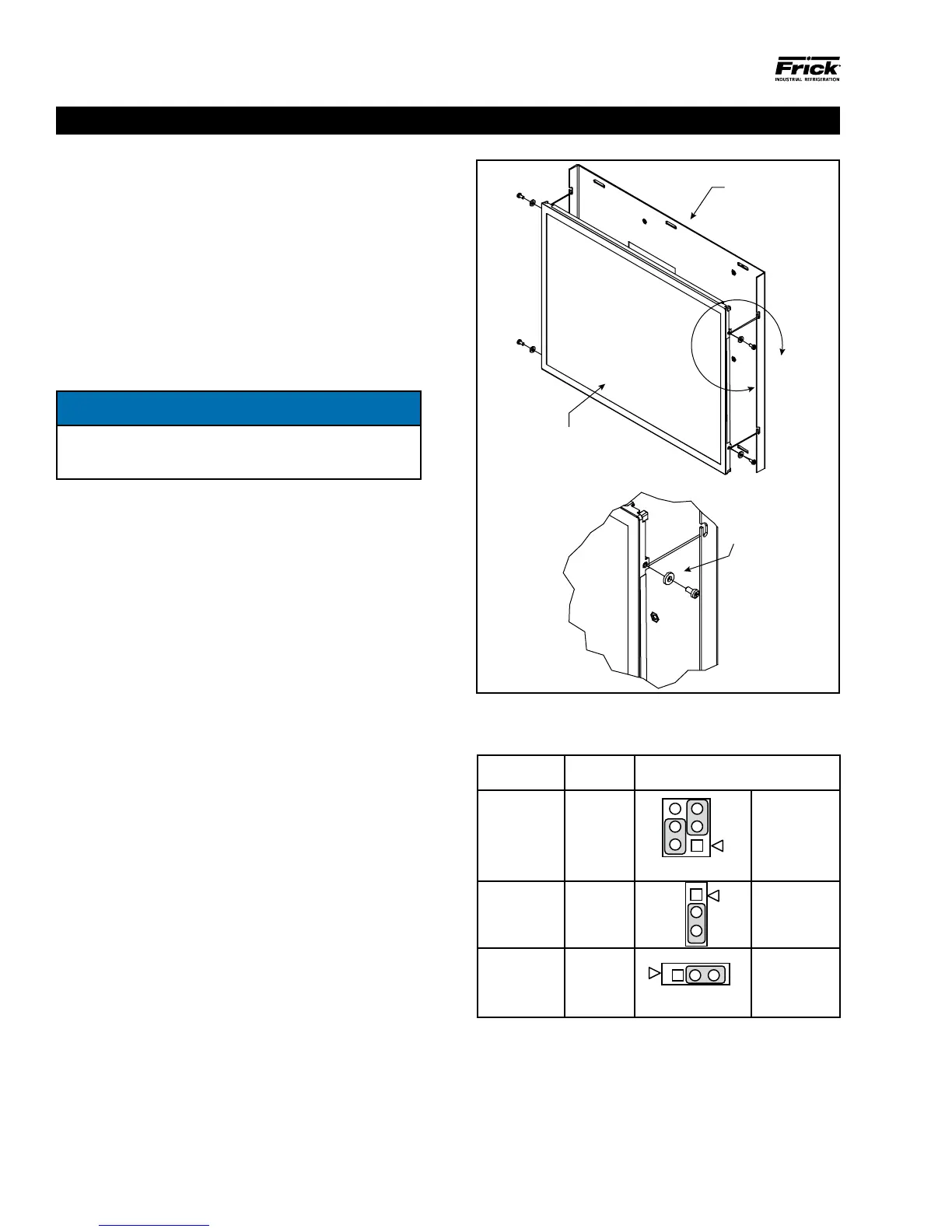
5. Loosen the four screws located on the display plate as
shown in detail A that follows.
6. Once all four screws have been loosened, carefully slide
the display out of the slotted mounting holes.
7. Remove the four screws and washers located at the
sides of the display.
8. Reinstall the new display by reversing steps 7 and 6, in
that order. Use the tool marks left by the hardware to
position the new display.
9. Reinstall the display plate back into position on the panel
door, and loosely reinstall the six hex nuts, do not tighten
yet.
10. Carefully reconnect the display and backlight connectors
on the back of the display.
11. Look at the display from the front of the panel door. Ensure
that the display is centered in the display opening. Once
centered, tighten the six nuts. Re-centering the display
may be necessary after these steps have been completed.
12. Verify the Q5 Processor Board Display jumper settings per
the table shown at the bottom of this page.
A
TAIL A
Display Mounting Plate
Display
INSTALL WA
DISPLAY AND MOUNTING
PLATE TO HELP WITH
DISPLAY VIBRATION
090.040-LD0001.eps
Figure 1. LCD Display Assembly & Mounting
Table 1. Q5 Processor Board Display Jumpers
Q5 MOTHERBOARD DISPLAY JUMPERS (LINKS)
Jumper Title Function Jumper Setting
CN1000
(LCD
Resolution
Selector)
18-bit
1024x768
(default)
6
4
2
5
3
1
3-5 Closed
&
2-4 Closed
JLVDS2
(Backlight
Level
Selector)
0– 5V
(default)
2-3 Closed
JLVDS3
(Backlight
Control
Mode)
PWM
Mode
(default)
2-3 Closed
(Refer to Section 5 for location of jumpers)
090.040-TB0001.indd
QUANTUM™ HD OPERATOR INTERFACE